Film cameras
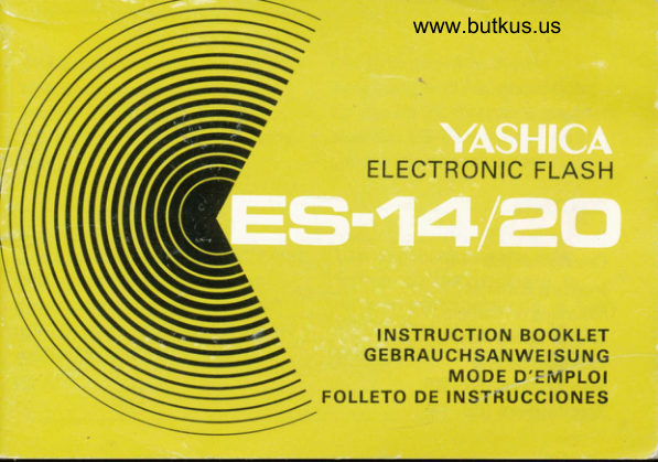
Yashica ES-14 / 20 instructions User manual
User manual for Yashica ES-14 / 20 instructions. 36 pages in German, French, Spanish. Read the original PDF, download or print a copy without registration.
36 pagesGerman, French, Spanish2.1 MB PDF
Loading your manual…Open PDF directly
Document details
- Brand
- Yashica
- Model / document
- Yashica ES-14 / 20 instructions
- Document type
- User manual
- Language
- German, French, Spanish
- Pages
- 36
- File size
- 2.1 MB
- Category
- Film cameras
- Document date
- Not specified in catalog
Search available document text
Find a term, then jump to its page in the original PDF. Image-only pages may not be searchable; check the PDF for exact wording and diagrams.
Page 1 · Read text
www.butkus.us


   ELECTRONIC FLASH


     INSTRUCTION BOOKLET
   GEBRAUCHSANWEISUNG
        MODE D'EMPLOI
FOLLETO DE INSTRUCCIONES
View original page 1Page 4 · Read text
www.butkus.us
The explanations in this instruc-   Die Erldrungen in dieser
tion booklet are given mainly      Anleitung sind hauptsdchlich
for the ES-20 flash, but the            ftir das ES-20 Blitzgerdt gegeben;
ES-14 flash is used in the same     aber das ES-14 wird auf die
way.                                gleiche Weise verwendet.


Les explications dans ce livret   Las explicaciones de este
d'instruction sont donn6es         folleto 'de instrucciones se
principalement pour le flash       refieren principalmente al flash
ES-20, mais le flash ES-14 est     ES-20, pero el flash ES-14 se
utilis6 de la mOme maniere.        emplea de la misma forma.
View original page 4
Page 6 · Read text
DESCRIPTION       DESCRIPTIONwww.butkus.us
BESCHREIBUNG     DESCRIPCION
 1 ) Batterv compartment cover      4)  lest button
    Batteriefachdecke    I                       Pru  f k nopf
   Couvercle de compartiment  i oile     Bou ton d'essai
   Tapa del compartimiento de las       Pulsador de comprobaci6n
     bater ias

2l Flash Head                   5) ON-OFF switch
    B litz ko of                            Ein-/Aus- Schalter
   Tete de  f lash                                                                                              I nterru pteu r
   Cuerpo del flash                      Interruptor ON-OFF

3) Exposure computer dial         6) Synchro cord socket
    Bel ichtu ngsrechner                  Synchronk abel bu cnse
   Cadran calcu lateu r d'exoosition        Prise de cordon synchro
    Dial computador de exposici6n       Enchufe para el cable sincronizador
View original page 6Page 8 · Read text
DESCRIPTION        DESCRIPTIONwww.butkus.us
BESCHREIBUNG      DESCRIPCION
1) Battery compartment cover      4) Test button
   Batteriefachdecke     I                       Pruf k no pf
   Couvercle de compartiment d pile     Bouton d'essai
   Tapa del compartimiento de las        Pu lsador de comprobaci6n
     bater ias

2) Flash head                    5) ON-OFF switch
   Blitzkopf                             Ein-/Aus- Schalter
   T6te de flash                                                                           I nterru oteu r
   Cuerpo del flash                        lnterruptor ON-OFF

J) Exposure computer dial         6) Synchro cord socket
    Bel ichtu ngsrechner                    Sy nch ro n kabel buchse
   Cadran calcu lateu r d'exoosition         Prise de cordon synchro
    Dial computador de exposici6n        Enchufe para el cable sincronizador
View original page 8Page 9 · Read text
Inserting
Batteries

lnsertion des
piles

Einsetzen der
Batterien

ColocaciOn de las
baterias
View original page 9
Page 11 · Read text
INSERTING BATTERIES

  1) Slide battery compartment cov-     As batteries weaken, the time
     er in arrow indicated direction.        required for the ready lamp to
  2t Install four AA batteries, taking       light lengthens. The batteries
     care that * and   are properly       should be replaced when recycl-                       -      positioned.                         ing time exceeds 30 seconds.  *     Alkaline batteries are recom-      Always replace all four.batteries
     mended for increased number of        together (2 batteries in case of
             f lashes per replacement and        ES-14).
      shorter recycl ing time.            When not employing the ES-20
  3) Slide the ON-OFF switch in       for extended periods test-fire
     arrow direction (red setting be-       the unit occasionally. This will
     comes visible); a faint whine will       prevent performance deteriora-
    be audible, and after a few        tion of the electrolytic capacitor
     seconds the ready lamp will      and keep the unit in best condi-
       light, indicating that the unit is         tion.
     '  ready for operation.    The ready lamp also functions
     as the test button. To test-f ire,
g    depress the test button.
View original page 11Page 12 · Read text
EINSETZEN DER BATTERIEN       www.butkus.us
 1) Batteriefachdeckel in pfeilrich-     zum Auslosen eines prrifblitzes
   tung schieben.                       den Prtifknopf.
 2) Vier AA-Batterien einsetzen,     * Wenn die Batterien schwdcher
   wobei darauf geachtet werden        werden, vergeht mehr Zeit, bis
   muB, daB + und -  in der richti-        die Bereitschaftslampe  auf leuch-   gen       Lage               sind.                                                        tet. -Die Batterien                                                                            ausge_                                                                   sollten*       groBere   Frir                 Blitzzahl und       wechselt                                            werden,                                          wenn   schnellere Blitzfolge werden       mehr als 30 Sekunden vergehen.dabei
   Al kal ibatterien empfoh len.           Alle vier Batterien mussen
3) Schieben Sie den Ein-/ Aus-       zusammen ausgewechselt werden
   Schalter in Pfeilrichtung  (die        (2 Batterien fur ES-14).
   rote Einstellung wird sichtbar);      Wenn das ES-20 ldngere Zeit  ein schwaches Summen wird        nicht benutzt wird, sollte man
   horbar, und nach einigen Sekun-      von Zeit zu Zeit einen prilfblitz
  den leuchtet die Bereitschafts_        auslosen. Dadurch wird verhin_
  lampe auf, um anzuzeigen, daB        dert, daB sich die Leistung des
  das Geriit betriebsbereit ist.              E lek  t ro lyt ko ndensators      ver  -  Die Bereitschaftslampe dient         sch lechtert.
  auch als Pr0f knopf. DrLlcken Sie                                                                     10
View original page 12
Page 13 · Read text
INSERTION DES PILES
  1l Pousser le couvercle de com-      fonctionne 6galement comme
     partiment d pile dans le sens de      bouton d'essai.
       la fldche.                   A mesure que les piles s'usent, le
  2) Installer quatre piles AA, en      temps requis pour que la lampe
     prenant garde de bien position-     t6moin s'allume devient plus
      ner les p6les + et _.                long. Les piles doivent 6tre  *  Les piles alcalines sont recom-       remplac6es quand la dur6e de
    mand6es pour accroitre le       recyclage d6passe 30 secondes.
    nombre d'6clairs par remplace-            ll  convient de tou jours rem-
    ment et pour une dur6e de       placer les quatre piles ensemble
      recyclage plus courte.                    (2 piles dans be case de ES-14).
  3) Pousser l'interrupteur dans le     Si I'on n'emploie pas l'appareil
    sens de la fldche (te reglage     ES-20 pendant une p6r'iode
     rouge devient visible); un faible       prolong6e, il faut faire des essais
     sifflement se fera entendre, et       d'6clairs de temps en temps.
    aprds quelques secondes  la      Cela 6vitera la diminution des
    lampe t6moin s'allumera,  in-         perf ormances du condensateur
     diquant que l'appareil est pr6t d       6lectrolytique et  maintiendra
11  fonctionner. La lampe t6moin        l'appareil en bon 6tat.
View original page 13Page 14 · Read text
COLOCACION DE LAS BATERIAS                                    www.butkus.us
    1) Deslice la tapa del compar-      comprobaci6n. Para disparo de
                                                          la      prueba, oprima el pulsador deti     timiento de las baterias en        direcci6n indicada por la flecha.       prueba.
   2) Meta cuatro baterias AA  te-    A medida que se agotan  las
      niendo cuidado de  colocar        baterias, se prolonga el tiempo
      adecuadamente el + y el -.             necessario para gue aparezca    *                                                                                                              la    Se recom iendan bater ias de      l5mpara indicadora. Debieran
        alcalino para un mayor n[mero        substituirse  las baterias cuando
      de destellos por juego y menos       el periodo de reciclo exceda los
       tiempo de recircu laci6n.             30 segundos. Substituya siempre
   3) Deslice el interruptor ON-OFF          las cuatro baterias (2 baterfas en
     en la direcci6n de la flecha         el caso de ES-14).
       (aparecer5 la marca roja); se oir5     Cuando no use el ES-20 por
      un ligero zumbido, y despu6s de     mucho tiempo, haga disparos de
        breves segundos, se encender5 la      co m probaci6n de vez  en
      lSmpara indicadora de  estar      cuando. Esto evitard el deterioro
       proto el flash para su operaci6n.      del funcionamiento  del caoa-
I     tambi6nLa lSmparacomoindicadorapu lsadorfunctionade      unidadcitor elect6nicoen su mejorV mantendr5condici6n.la                                                                         12
View original page 14Page 15 · Read text
Mounting on Camera
 Befestigung auf der Kamera
 Montage sur I'apPareil Photo
 Montaje sobre la c6mara


                Unit side plug
                 Stecker auf der Gerdteseite
                    Prise lat6rale de l'appareil flash
                Enchufe lateral de la unidad
                Camera side plug
                   Stecker auf der Kameraseite
                     Prise lat6rale de l'appareil Photo
13             Enchufe lateral de la cdmara
View original page 15Page 17 · Read text
MOUNTING ON CAMERA
    1) C"."rur without hot-snoe         NOTE: The synchro'cord of
     Slide the ON-OFF switch to        this unit is detachable. When the
    OFF (black setting becomes  visi-      synchro cord is removed, the
     ble), plug one end of  the       unit provides direct contact.  lf
     synchro cord into the synchro      the unit is inserted into the
     cord socket of the flash unit,     accessory shoe with   the
    and insert the tlash into the     ON-OFF switch in the ON posi-
     camera accessory shoe. Plug the       tion it may flash, so the switch
     other end of the synchro cord      should always be in the OFF
      into the 'X' svnchro terminal of        position when attaching the unit
     the camera. lf  tfre camera fea-       to tne camera.
      tures a sync selector, make sure
         it is set at 'X'.
  2 Cameras with hot-shoe
     For cameras with hot-shoe the
      synchro cord is not used.
     Simply insert the  f lash unit into
      the camera accessory shoe (hot-
      shoe ).15
View original page 17Page 18 · Read text
BEFESTIGUNG AUF DER KAMERA www.butkus.us
  Kameras ohne M itten kontakt        wird das Synchronkabel  nicht
  Stellen Sie den   Ein-/Aus-       verwendet. Schieben Sie einfach
  Schalter auf OFF (die schwarze      das B  I itzgerdt in den Zu behor-
  E  i n st ellu ng  wird   sichtbar)  ,      schuh (mit Mittenkontakt) der
  stecken Sie das eine Ende des       Kamera.
  Synchronkabels in die Syn-                                       . ItS Das Synchronkabel
  chronkabelbuchse des Blitzg+        dieses Gerdts kann abgenommen
  rdtes und schieben Sie das     werden. Wenn das  Syn-
  Blitzgerdt in den Zubehorschuh       chronkabel entfernt ist, gibt das
  der Kamera. Stecken Sie das      Gerdt direkten Kontakt. Wenn
  andere Ende des Synchron-      das Gerdt mit eingeschaltetem
  kabels in den "X"-Kontakt  der        Ein-/Aus- Scha lter ei ngescho-
  Kamera. Wenn die Kamera einen     ben wird, kann ein  Blitz
  Synchron isationsumschalter  hat,       ausgelost werden, weshalb der muB dieser auf "X"  gestellt       Schalter bei der Befestigung auf
  weroen.                            der Kamera immer ausgeschaltet
  Kameras mit Mittenkontakt             sein sollte.
   Frlr Kameras mit Mittenkontakt
                                                                    16
View original page 18Page 19 · Read text
MONTAGE SUR I'APPAREIL PHOTO
       'l) Appareils photo sans contact         griffe A contact direct, le cordon
           d  i rect                           synchro est inutile. ll  suff it
      Pousser   l'i nterru Pteur    sur         d'ins6rer l'appareil flash dans la
    OFF (arr6t) (le reglage noir        griffe accessoire de l'appareil
       devient visible), brancher une       photo (contact direct).
       ext16mit6 du cordon svnchro       Ni  'i r-:o Le cordon synchro de
       dans la prise de cordon synchro      cet  appareil est  amovible.
      de l'appareil flash, et ins6rer le       Lorsque le cordon synchro est
         flash dans la griffe accessoire de         enlev6, l'appareil permet le con-
           l'a p pa rei l  photo.  Brancher        tact direct.Si I'appareil est ins6r6
        l'autre extr6mit6 du cordon      dans la griffe d accessoire avec
       synchro dans la prise synchro        l'interiupteur en position ON
      "X" de l'appareil photo. Si         (en-circuit), il risque de d6clen-
         celui-ci est muni d'un s6lecteur       cher un 6clair, aussi le com-
        synchro, s'assurer qu'il soit bien       mutateur doit toujours 6tre d la
         16916 sur "X".                        position OFF (arrdt), lorsqu'on
    2l Appareils photo avec contacr       monte l'appareil sur  I appareil
         direct                               photo.
      Pour les apparei ls munis d'une
 17
l_
View original page 19Page 20 · Read text
MONTAJE SOBRE LA CAMARA                                www.butkus.us
'i)   CSmaras sin zapata de contacto       lzaoata de contacto directo)
   directo                                 accesoria de la cdmara.
   Deslice el interruptor ON-OFF          hil]:.'  Puede quitarse el cable
   hacia OFF ( aparecer5 la marca       sincronizador de esta unidad.
   negra), meta un extremo del      Cuando se quita el cable sin-
   cable sincronizador en el en-       cronizador, la unidad proporcio-
   chufe correspondiente del flash      na contacto directo. Si se mete
  y meta el flash en la zapata        el aparato en la zapata accesorio
   accesoria de la cdmara. Meta el      cuando el interruptor ON-OFF
   otro extremo del cable sincroni-      se halla en posici6n ON,. ec
   zador en el terminal sincroniza-        posible que destelle, por lo que,
  dor 'X' de la cdmara. Si  la      al colocar la unidad en  la
  cdmara tiene un selector sin-      c6mAra, el interruptor debiera
   cronizador, asegtrese de que        estar siempre en posici6n OFF.
   esta colocado en 'X'.
   CSmaras con zapata de contacto
   directo
  No se usa el cable sincronizados
  con las c5maras con zapata                                                                18
View original page 20
Page 21 · Read text
SHUTTER SPEED           EINSTELLEN DER VER-
    SETTING                   SCH LUSSG ESCHWIN DIG KE IT
       .  Leaf-type shutter cameras        s Kameras mit ObjektivverschluB
q     When using this unit with a     Wenn dieses Gerdt mit einer
         leaf-type shutter camera, perfect      O b jektivverschluBkamera  ver-
        svnchronization can be obtained      wendet wird, konnen alle Ver-
       at all shutter soeeds. With the          schl uBgeschwi nd igkeiten perfekt
        so-called " EE" camera, how-        synchronisiert werden. Bei einer
        ever, the method of use varies       sogenannten EE-Kamera Sndert
      with the type of camera.           sich die Verwendungsmethode
   o Focal-plane shutter cameras            mit dem Kameratyp.
      With  f ocal-plane shutter cam-   e Kameras mit SchlitzverschluB
        eras, the "X"  setting on the      Bei  SchlitzverschluBkameras
        shutter speed dial indicates the        zeigt die X-Markierung auf dem
        shutter speed for synchronizing        VerschluBzeitenw6hler die Ver-
      with an electronic flash unit.      schluBgeschwindigkeit fir
      Always set the shutter speed       Sy nchronisation mit  einem
        dial to the "X" or slower set-        Elektronenbl itzgerdt an.
        ting. However, the method of
        use varies with the camera type.
 19
View original page 21Page 22 · Read text
REGLAGE DE V,ITESSE      ADJUSTE                                www.butkus.usDE LA VELOCI-
D'OBTURATEUR          DAD DEL OBTURADOR
o Apparei ls photo d obturateur du     * C5maras con obturador tipo
  type d lame                          lSmina
 En  utilisant cet   appareil      Cuando se usa esta unidad con
  avec un  appareil photo       una camSra con obturador tioo
 A obturateur  i  lame, u ne       lSmina, puede conseguirse una
  synchronisation parfaite peut        sincronizaci6n perfecta en todas
   6tre obtenue d toutes les vitesses       las velocidades del obturador.
  d'obturateur. Avec l'appareil        Pero, con la asi llamada c5mara
  photo appel6 "EE", cependant,       "EE" , varia el m6todo del uso
  la m6thode d'utilisation varie       seg0n el tipo de la c6mara.
  avec le type d'appareil photo.   o C5maras con obturador de plano
c Appareils photo d obturateur A         foca    I
   olan focal                        En las cdmaras con obturador de
  Avec des appareils photo d obtu-       plano focal, el ajuste 'X' en el
  rateur a plan  f ocal, le 169lage        dial de la velocidad del obtura-
  "X" sur le cadran de vitesse       dor indica la velocidad de 6ste.
  d'obturateur indique la vitesse
  d'obturateur pour la synchroni-
   sation.                               n
View original page 22
Page 23 · Read text
Exposure Setting
 Be  I ichtu ngseinstell u n g
 Reglage d'exposici6n
 Ajuste de la exposiciSn


21
View original page 23
Page 25 · Read text
EXPOSURE SETTING
   1) Align the triangular mark on the       to-subject distance =  correct
,     exposure computer dial with the       aperture. As the guide number
    ASA/DlN rating of the  f ilm      of this unit is 20 (ASA 100 in
      loaded in the camera.                  meters), with a flash-to-subject
  2) Determine the flash-to-subject        distance of 5 meters the correct
      distance and select the figure       aperture is F4.
     corresponding to this distance
     on the exposure comPUter dial.   CAUTIONS FOR HANDLING
                                      is indicated           correct                 aperture     The
                                    flash-to-                                     * When the unit is not in use,    I                above the              dial    on the
      subject-distance scale. The aper-       always set the ON-OFF switch      I                                                    (black                                                                                        visible).                                                              setting                             OFF                                     to         can               also be figured     ture                              from    *                                                                             the                          I                                                      from                                 Remove                                                              batteries                                               the              number.                    The relation-      the guide
                                                                                                                              is      ship between the guide number,       comoartment when the unit
     aperture, and flash-to-subject       not in use for a long period of
      distance is as follows:                     time.
     Aperture x flash-to-subject dis-
     tance = guide number (GN);
                                                                             f lash-23   therefore, guide number;
View original page 25Page 26 · Read text
BE L ICHTUNGSE   I NSTE L LUNG        www.butkus.us
   1) Stellen Sie die dreieckige Mar-       Blende x Entfernung Blitzgerdt-
      kierung des Bel ichtungsrechners       Objekt = Leitzahl, also Leitzahl
     auf den ASA/DIN-Wert des in     + Entfernung Blitzgerdt-Objekt
     der Kamera verwendeten Films     =  korrekte Blende. Da die
        ein.                                  Leitzahl dieses Geriites 20  ist
). 2l Bestimmen Sie die Entfernung      (ASA 1OO in Metern), ist Blende
     zwischen Blitzgeriit und Auf-     4 bei einer Entfernung Blitzge-
     nahmeobjekt und suchen Sie die        r6t-Objekt die richtige Blende.
      d  i eser  Entfernung entspre
     chende Zahl auf der Skala des   BEDIENUNGSH INWEISE
                                         rich-      Belichtungsrechners.                   Die                                     *  Wenn das Gerdt nicht verwendet             t                                  der                     auf     ige B lende steht                                     wird, muB der   Ein-/Aus-    Skala riber der  Entf ernung                                                    OFF      B  I itzgeriit-Auf nahmeobjekt. Die       Schalter unbedingt auf
    Blende kann auch liber die       (schwarze Einstellung ist sicht-                                                             gestellt                                                      werden.               errechnet                       werden.      Leitzahl                              Das    *  bar)                                                Batterien                                                         miissen entfernt                                 Die       Verhai                                  Leitzahl,              zwischen                  ltn is
     Blende und Entfernung Blitzge       werden, wenn das Gerdt ldngere
       rdt-Auf nahmeobjekt  ist wie folgt:        Zeit nicht benutzt wird.                                                                   24
View original page 26Page 27 · Read text
REGLAGE D'EXPOSITION
  1 Aligner le repdre triangulaire du        suite, Nombre guide * distance
      cadran calculateur d'exposition        flash au sujet = ouverture cor-
      avec la valeur ASA/DlN du film        recte. Comme le nombre guide
      charg6 dans l'appareil photo.        de cet appareil est 20(ASA 100
   2) D6terminer la distance du flash     en mdtres), avec distance flash
    au sujet et choisir le chiff re      au sujet de 5 mdtres l'ouverture
      corresoondant e cette distance        correcte est F4.
     sur le cadran calculateur d'ex-
      position. L'ouverture  correcte   PRECAUTIONS POUR LA
      est indiqu6e sur le cadran au-   MANIPULATION      dessus de l'6chelle de distance                                      {                                     *  Lorsque l'on n'emploie pas l'ap       flash au sujet. L'ouverture peut
      6galement 6tre trouv6e depuis le        par.eil, 169ler tou jou rs  l'inter-
      nombr+guide.                          rupteur sur OFF (arr€t) (reglage
    Le rapport entre le nombre-        noir visible).                                     *  Enlever les piles du compar-      guide, l'ouverture, et la distance
      flash au sujet est comme suit:      timent lorsqu'on n'utilise pas
     Ouverture x distance  f lash au        l'appareil pendant une longue
25    sujet = nombre guide (NG); oar        p6riode.
View original page 27Related documents and language editions
YashicaPDF
Yashica Quick-lite Pro 100
User manual
15 pages · EnglishRead →
YashicaPDF
YASHICA CS-201 instructions
User manual
22 pages · German, French, SpanishRead →
YashicaPDF
Yashica Cs 201
User manual
19 pages · German, French, SpanishRead →
YashicaPDF
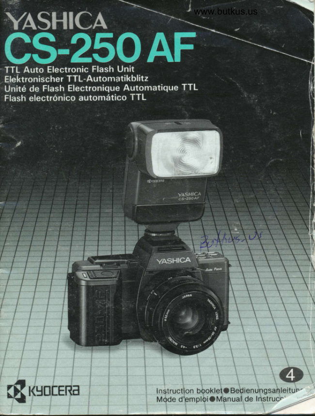
Yashica Cs 250 AF
User manual
68 pages · German, French, Spanish, EnglishRead →
YashicaPDF
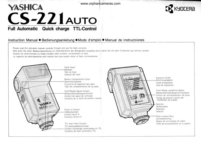
Yashica CS-221
User manual
11 pages · Not specifiedRead →
From the M. Butkus archive. Original publisher and archive notices are retained.
Check the model and edition against your equipment.
PDF verified 2026-10-10.