Sewing machines
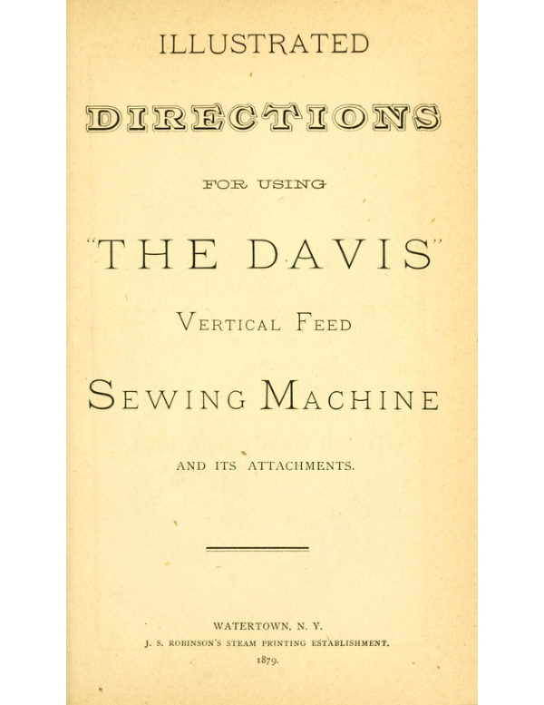
Davis Vertical Feed (1879) — User manual
User manual for Davis Vertical Feed (1879). 65 pages in English. Read the original PDF, download or print a copy without registration.
65 pagesEnglish16.9 MB PDF
Loading your manual…Open PDF directly
Document details
- Brand
- Davis
- Model / document
- Davis Vertical Feed (1879)
- Document type
- User manual
- Language
- English
- Pages
- 65
- File size
- 16.9 MB
- Category
- Sewing machines
- Document date
- Not specified in catalog
Search available document text
Find a term, then jump to its page in the original PDF. Image-only pages may not be searchable; check the PDF for exact wording and diagrams.
Page 3 · Read text
DIRECTIONS

                    FOR OPERATING

THE DAVIS SEWING MACHINE.


     Before the machine leaves our hands.   it has been  minutely inspected. and
every mechanical defect corrected   :   it has been tested with various sizes of thread
ranging from No. 40 linen to 150 cotton, and found  to work satisfactorily in every
respect.  \\’hen unpacked, the machine should be found  in complete running or-
der, with a sample of work under the presser foot, as  it came from  the hands of
the inspector, and the machine threaded  ready  for sewing.   Parties who have
never seen the machine before.  should  first observe how   it  is threaded—but  if
from any cause the machine should bet‘ome unthreadcd in transportation. the ope-
rator should observe the directions for threading given  hereafter.


                        OlLlNG THE MACHINE.

     This is the most important rule to be observed. for care in oiling the hearings
                                                                                                            oil the insures durability and ease of motion, and prevents premature wear.  To
 inside work of the head raise the needle bar to  its highest point and put one drop
 in each of the five holes on the head. in front and rear of the three bars; the same
 quantity in the holes on both ends of the arm and on top of and on the back side
 of the back hanger. (which  is between  the arm and hand  wheel) and a drop on
 the lower end of the hack hanger to lubricate the slides.   l’ut one dropin the hole

                                                                                                                                                                                                                                               ; in centre of bed plate, under the arm, and on  the journal  of the balance wheel
 a drop on the hearingr at each end of the pitman. and of the treadle.
      All places where the machine should he  oiled  are  indicated by the letters A
 BCDEFGHI]KLEINOtYl’.inFig.lpage2.
    Run the machine several revolutions swiftly, and the oil will be distributed on
 the hearings: then wipe  off  all  excess of  oil.  that  it may not  soil  the work or
 clothing.   If the machine runs hard by means of poor  oil, or  if  it becomes gum-
 my by long standing. use a little kerosene oil. which  will soon  reniove the gum.
 after which apply a little good fresh oil.
View original page 3Page 5 · Read text
THREADIllG THE  llClIIllE.

                    SEE FIGS. 2 AND  3, PAGE 4.

     First raise the needle bar to its highest point: place  the  spool  of thread on
the spool pin 78 (Fig. 2).  Pass  the thread under the check  spring 82  Fig. 3),
then over and around the tension wheel  87 once  only   ;  then  through the thread
guide 90(Fig. 2); then through the thread tube  123  (Fig. 2»;  then through the
eye of the take up 97 (Fig.  2), lamb (y'llu' slur/1k;  then  through  the eye of the
needle, leaving the thread about three inches long.


                      SETTING THE NEEDLE.

                            Sm:- Flo. 6. PAUL“. 4.

    Hold the needle between the thumb and first  linger of the left hand and pass
the point down through the slot in the throat  plate  47:  then  pass the shank up
through the hole in the needle yoke t21. with the tint  side  to the needle bar, and
hold  it in place by turning the needle nut 122 to the right.
   Now observe a mark or  cut  tiled across the edge  of the  needle bar about
one inch from the top.  Turn the hand wheel 54 tsee  Fig. 2) so as to bring this
mark down on a level with  the top of the  head, and lzold it t/zere.  Loosen  the
nut 122. and place the needle so the eye  will be on a  level with  the throat plate
47.  Secure  it firmly by  the nut  122.  The  side A  of the combination Screw
Driver (Fig. 4, Page 4) can be used to tighten the nut.
    The bottom of the loop should be one-eighth of an  inch below  the point of
shuttle just as  it enters the loop.    ll very coarse cotton. linen or silk be used, the
needle should be set a little lower than the directions indicate, and a little higher
for very fine thread.


                   TO REMOVE THE NEEDLE.

    Loosen the needle nut 122, and the needle can readily be taken out.


                     THE THROAT PLATE

is provided with two slots.  The larger one is adapted to the use of a No. 3 or 4
needle, the smaller one for all  smaller  sizes.  To adjust the throat plate, loosen
the screw 48 (see Fig. 6, page 4) which holds  it in  place. and  slide  the plate out,
reverse it and slide it back. taking care to have the plate in such  position that the
needle in going down  will  pass close to the front end of the  slot, but without
touching the end or either side.
View original page 5Page 7 · Read text
WINDING THE  BOBBlll.

                            SH”. FIGS.  7 AND  8, PAGE  6.

    The bobbin winder will be found attached to the  right leg of the stand. and
 held up by a spiral spring;  this spring should always remain attached both to the
 winder and the table leg". holding the winder down to the large wheel when in use
 and also holding  it back when not in use.
       \\'ith the belt off bring the winder down  so that  the spooler rubber 39 will
 come in contact with the balance wheel 3 (Fig. 7).

    Turn the wheel until the feed  lever 36  reaches  its  right hand extremity, as
 shown in Fig. 8; place one end of the bobbin in the socket of the revolving spin-
 dle 26. and the other end in the socket of the step 30 (Fig. 8).
    Now place the  end  of the thread  between  the brass  bobbin head and the
 socket of the spindle 26   ; thence in hook of the feed lever 36.
    Turn  the  l:)alance-wheel {award you. holding the thread smoothly by the
 hand. as shown in Fig. 7.  The feed lever 36 will distribute the thread  evenly on
 the bobbin.
     W'hen sewing. the bobbin winder should always be up against the table leg,
‘as shown in Fig.  I, Page  2.
View original page 7Page 9 · Read text
THREADING THE SHUTTLE.

                                     Sl—Zli FIGS.  9.  10 AND  it, Pam:  8.

     Depress thc'end of the  latch 72 (Fig. IO) with  point of bobbin. as shown in
 Fig. 9. raising the latch to a perpendicular position as shown in Fig. 10; place one
 end of the bobbin in the hole in front end of shuttle, allowing a little loose thread
 from the bobbin to hang over that side of the shuttle to which the latch is attach-
 ed.  The thread should draw from lower side of the bobbin.

     Hold the bobbin in place, as shown in Fig. 10;  close  the  latch  as shown in
 Fig.  II.  The latch forms the distributing bar as well as holding bobbin in place.
              ' Thread downward through the staple 76 (Fig. II) and out through the large
 slot, leaving the thread about three inches long.

    NOTE—[iv sure Mm! l/ze [ale/z  is closed andfaslcnm’ securely before placing
1/15 Mull/r in  1/18 mac/zine.


                      SHUTTLE TENSION.

    The tension on the shuttle thread  is formed by the pressure of the pad spring
on the under side of the bobbin. and this is regulated by the small screw 75 (see
Fig. I!) in point of shuttle.                    ’
    Turn this screw  to the mgr/11 to increasv the  tension, and  to the It]! 10 de-
crmse it, using the small point B of the combination screw driver(Fig. 4, Page 4).
   When the machine leaves our hands. the tension  in the shuttle  lzas been set
about rig/ll for all kinds qf war/a mu! ”Maui, and therefore rare/y m'm’s allrrz'lgg.
View original page 9Page 11 · Read text
T0 PLACE THE SHUTTLE  IN THE MACHINE.

                                       Star, FiG.  12, PAGE  10.
    W'ithdraw the front rnce cover 45, and place the shuttle between the prongs
67 of the shuttle carrier,/mz'11/firsl and toward t/u' n/u'ralor.
   NOTE—it  is sometimes more convenient to withdraw the hack race cover 46,
and put the shuttle in its place when the prongs are in the hack  part of the race.
This is especially the case when some of the attachments are in use.


                 T0 DRAW UP THE LOWER THREAD?

    Hold the upper thread slack with the  left hand;  turn  the hand wheel m'er
fromyou with the  right hand  slowly, until the needle has passed down and up
again to its highest point.  The upper thread will form a loop in  the  shuttle race
through which the shuttle will pass, and the needle, when  it  rises, will draw the
lOWer thread up through the  slot  in  the throat  plate.   Close the race cover (or
 covers,  if both have been withdrawn, as shown  in Fig. 12) and draw the ends of
 the thread back.

                                                                                                                             it is done   NOTE—A'mwr rm: ilw Afar/zine will:  1‘qu ma' (overs nfien, except
 with the hand, and ray s/ow{y.
View original page 11Page 13 · Read text
COMMENCING T0 SEW.

    The Machine being fully threaded above and below. and lowvr thread drawn
up. as heretofore  explained. the  presser  bar  102  raised, and  needle  bar  at  its
highest point (as shown in  l‘ig.  2. page 4). you are ready to sew.
     Place the goods under the presser bar, with the needle directly over the point
where you wish to begin the stitching; lower the. presser bar by the presser lifter
 too. (see Fig.  12. page 10) and start  the machine by turning the hand wheel over
from you with the right hand.
                                                                             0
     NU'I'E.—lf  it  is found difficult to get a regular and easy motion to the treadle
 at first,  it should be learned by running the machine Info)? 17  11a: [mm ”traded,
with the Sim/M: (ml and with the prayer liar raised.


           TO REMOVE THE WORK FROM THE MACHINE.

     Stop the machine with the needle at its highest point; take hold of thethread
 at A, (see Fig.  13. page 12) and draw two or three inches off from the tension and
 spool. leaving the thread “slack"; raise the presser bar and draw the work steadily
 out from you toward the back  part  of the machine;  cut  the threads about two
 inches from the needle.
View original page 13Page 14 · Read text
THE  TENSIQONS.

    The object to be attained is to have the stitch alike on both  sides of the fab-
 ric.  This is accomplished by means of the  tensions, or strain upon both threads.
The tension upon both threads should be as  nearly alike as  possible, and tight
enough only to make a  smooth. firm seam.    If the threads are the proper size
fm‘f/ze'matvrz'a/ used, and both tensions right,the threads will be drawn and locked


 ”1111717  Jz'a’v qf  f/u' goods, thus:
 loops on the under side.  On the contrary,  if the upper tenson  is 100 [lg/[f (or the
 shuttle tension too loose) the 11/1/747- f/zmm/ ~zu1'//  {if slung/1!  0/1.  1/11' ztp/wr side of                                                    '                                                                                                                                                            .
 the goods, thus:      7            2     fi’  the lower thread showing in loops on the upper

 side.
    To {lg/clan 1/10 ujipcr fermion, turn the tension nut 85 (See Fig.  I 3 Page 12)
 to {lie rig/ll.
    To [norm  1/10  11/2/50' tension, turn the tension nut In My 14/7.
    As the shuttle tension has been set right for general work when  the machine
 leaves our hands, as before explained, any needed regulation  of the stitch  in this
 respect should ordinarily be made by changing the upper  tension.    If, however,
when the upper tension  is regulated so the lock is in the centre of the goods, both
 threads appear to be loose, and the stitches and seam not smooth and firm, the
 S/Hlfl/L' {fusion  is [00 loose, and should be fly/11mm! by turning the  tension screw
 75 to the  right, (See  Fig. H, Page  8) then tightening the upper tension corres-
 pondingly.
       If the under thread cannot be properly drawn up without having the upper
 tension so tight that the thread breaks, or  if when the tensionsare evenly balanced
 the goods are “drawn" or “puckered." (this  will occur only in sewing very light
 and “slazy” fabrics) the slut/flu tension  is too fly/11 and should be loosened by
 turning the shuttle tension screw to  the  left;  then  loosen  the upper tension to
 correspond.
   NOTE—“The Davis" rut/111371? lass ("lift/{gr qf [ms/"011 than rug/011157 mac/zine,
 in fact no change is necessary in any ordinary work.
    The above particular explanation  is given that every operator mayfu/{y 1m-
 a’z'rs/lum’ 1/11? [Wind/Mrs ‘lf l/zr lens/mm.
View original page 14Page 15 · Read text
LENGTH OF  STITCH.
   The length of stitch  is regulated by turning the stitch adjuster knob 139 (see
Fig.  13. page 12) to the right or left.  Turn the knob  to the  right to shorten the
stitch.  Turn  it to the. left to lengthen’thc stitch.


                    T0 TlGHTEll THE BAND.

      If the band becomes loose so as to  slip, cut  a short  piece  off and hook the
ends together again.    It will be found necessary  to shorten   it  several times, and
until the “stretch" will all be taken out.


                     SlZE OF NEEDLE  AllD THREAD.

    Machine sewing does not require so coarse  a thread as hand sewing—every
stitch being double.  The size of the thread to be used must determine the size of
the needle.  The following sizes of  Silk. Cotton and Linen are used with the sizes
of needle affixed, viz:  For—

200 to 100 Cotton
100  “  90      “  oroootoooSilk
 90“   70          “   00 “  o  “
 70 “   50          “    0 “  B  “      or too to 90 Linen
  50 “   30         “   B “   I)  “       “   90 to 70   “
 30 “   ”to          “  D “ER  “       “   70 to 50   “
  to                 “   E “ FF  “        “   50 to 4.0   “
    The foregoing may be varied slightly to  suit the  fabric used.  Good l/trmds
are essential to good work.
    “The Davis" will run coarser flirt-ml  2)! jim' need/e than any other machine
 in the market.  This fact  is frequently  of  great advantage, especially in  leather
 stitching.
View original page 15Page 17 · Read text
GAUGE AND SELF SEWER.
                                            81-31: fins.  14. 15   .\.\'1)  16.
    Attach the gauge and self sewer to the machine by the gauge screw 145. with
the loop B of the sprintr A on the  “ toe " C  of the presser bar  102. as shown in
Figs. 14. 15 and  16.

     Set the gauge 149 as  far from  the needle  as you  desire  to  have the line of
stitching from the edge of the goods.   l’lthe  the goods under the spring A. and
under the needle and presser bar with the edge or edges against the gauge; lower
the presser bar and sew as usual.  The spring A  will  hold  the goods smoothly
up to the gauge, thus insuring a perfectly straight seam.
     Fig. 16 shows the operation of sewing a curred pieCe on astraight one.  This
attachment  is invaluable  in sewing  straight  or  parallel  Seams. curved edges on
straight, or two curved edges together. and in an almost  inconceivable  variety of
similar work. as all am  1’1' dour cud/mu! [ms/171g by using  this attachment.

                                                             149 used alone when    N111E.——The spring\ can be det.lCllt d and the gauge
desired.
View original page 17Page 19 · Read text
HEMMING.

                        SEE Fios. 17 AND  18.
    Attach the hemmer securely to the machine by the gauge screw 145, with the
end  of the  scroll A closa-  to  the  stripper   l‘) of the  presser  l)ar.(see Fig. t7.page
18.) and in such position that the  line of Stitching will he on the edge of the hem
as desired.  Enter the edge of the  cloth in  the hemmer, drawing  it forward and
back a little until the scroll  is tilled and the hem  evenly turned.   Fig.  17. page 18
shows the hemmerattached, with  cloth  inserted  in  proper  position.  Lower the
presser bar, and meeed  115 with ordinary Work, guiding the material  as shown in
Fig. 18 above, so as to keep the scroll  tilled.
View original page 19Page 20 · Read text
TO MAKE A HEM AND STITCH 0M EDGING.

                            SEE FIG. 19.
    Attach the hemmer and insert the goods as shown in Fig.  17. page 18; place
the ed lsrintrh over the hemmer and under the needle and   resser bar;  lower the
                                                                                                                                                                                  l      .P resser bar and  iroeeed as wnth  l‘tt’lllllllnfl'.o h(fuidinw3) the edwimTcs  6 as shown in Fi isr.
View original page 20Page 22 · Read text
FELLING.

                                      S121: F1os.2o,21 AND 23.
     Place the two pieces of material together, having the edge of the under piece
project beyond the edge of the upper far enough to admit of  its being turned over
the edge of the upper and  stitched down,  as hereafter explained.   (\\’ith such
goods as ordinarily require felled seams, the under edge should project about one—
ezg/zflz of in:  171511.)

     Pass the goods through the hemmer. as shown in Fig. 20. page 21   ; orthrough
the gauge and  self-sewer, as shown above  in  Fig. zl—turning  the edge  of the
lOWer piece over the edge  of  the upper. and  stitching  it down  as shown in both
Figs. 20 and  21.   In  this operation  the edge  of the upper  piece  511011111 not be
turned, but should be held close to the fold in the lower piece.  The edge of the
lower piece should be turned just enough la be fastened  17)! NM 5mm,-  if turned
over farther than necessary the edge can be trimmed close to the seam.
View original page 22Page 23 · Read text
FELLlllG.

    Remove the hemmer or  self-sewer; spread  the goods out smoothly at the
seam and stitch down the edge of the fell. as shown in Fig. 22 above.
   NOTE—In the operation  illustrated  in Fig. 20, use either the No.  i, No. 2 or
3B" hemmer, according to thickness of material.
    By using the gauge and self-sewer, as in Fig. 21,page  22, a  fell of any width
can be made. and with any kind of goods, or arms: 5mm: and other/elk.
      If  it is desired to show both edges of the fell, as  at A, in  Fig. 22, a hemmer
should be used in  the first  operation. having the edge of under  piece project far
enough so a rqgu/ar [mu will be made; then spread out the goods and stitch the
other edge as in Fig. 22.
View original page 23Page 24 · Read text
QUILTING.

                                              Sui-1 Flu.  23.

    The quilter ISI,  is attached by passingr the rounded part  through the  hole in
the presser bar made for that purpose, as shown  in Fig. 23.
                             ’
    Adjust  it to the. right or left. flCt‘Ol'dlng  to the distance required between the
lines of stitching;  fasten  it by the small screw H3, in the back side of the presser
bar, having,r the guide or  flat part of the quilter raised  just  far enough above the
bed of the machine to allow the free passage of the work under  it.

    Guide the work so as  to keep the seam  last  stitched  directly under  the Hat
part of the  quilter.  This  insures the  seams  beinic,r  perfectly  straight and equal
distances apart.
View original page 24Page 25 · Read text
BRAIDING.

                   To Thread  and Attach the Braider.
                                     Sir,   l~'11:.  24.
    Thread the braid through the slot from the under sideol the bt‘aitlet'.allowing
the braid to pass out through the slot. bark on the upper side about half an inch.
Three sizes of  slots are made to areonnnodate  the size of braid to be Used.  The
 braid should pass freely through  the slot.    .\ttat‘l1  the braider  to the maehine St)
 that the slot used will be directly  (H'et‘ the slot  in the  throat  plate. and  the needle
 pass down  in the little hole at the front edge of  the  slot  ail/11111!  four/1171.5,- then
fax/cw l/ze (Trait/fr yum-(fr with the braider srrew 146: draw  the  shuttle  thread
 up through the braid as e\'plained on page  to. for “drawingr up the lower thread."
      Hih'ct the upper tension strong. and the lower tension light. so that sewing on
 two or three thicknesses of muslin. the knots formed by the lock would appear at
 the top.
    The patternrsbould be 'ntarl\'erl or Vstamped on  the “ wrong,r side " of the ma-
 terial.
View original page 25Page 26 · Read text
BRAlDlNG.

                            SEE Fm.  25.

     Place the goods on the braider and under  the presser bar, with  the jut/turn
side  11/5. and so the needle  will be  directly over the  point where you  desire to
commence braiding; lower the presser bar and sew  as  usual. guiding the ma-
terial  so the needle will follow the pattern.  The braid  will be stitched to the utt-
der side of the goods, as shown in Fig. 25.
    To make a short or right angle turn (L), sew up to the point of turning; stop
the machine while the needle is rising, and before  it gets out of the cloth—slightly
raise the presser foot and swingr  the  cloth round on  the  needle.  Care must be
taken in turningr the cloth while braiding,  not to pull the  needle,  thereby causing
it to strike on the side of the plate and break.

   Nt)’l'li.—All the attention that need be given  to  the  braid  is  to have  it  pass
freely and smoothly up to the braider.  The bunch or spool of braid may lie in the
lap of the operator.
View original page 26Page 27 · Read text
“I Tilli   ll     I'
                            lili’.


        DIRECTIONS
                                              5151: Fm.  26.
      I’laCe the tucker on the machine with the creaser spring or arm A over the
                                                                                   1} ax far frnm  f/u' need/e as [110presser foot, as shown in Fig. 26;  set the gauge
twill/1 ‘Zf lm‘l‘ a’exz'rm’; fasten  it firmly by the gauge screw; loosen the nut C. and
                                                           nerd/v  It)  1118 hf! as themove the creasing blade I) jm‘l  lzuz'n‘ as far [rum  l/u'
gauge B is to the right.  This will make tucks ruff/mu! any s/mt'e between them.
                                                                               11.1 mar/1  y/.t()',/lt')'-/.)'(UN  [lie need/e as  flu- If Space  is desired move  the  creaser
s/nza' Ti’altfc’d; secure the creasing blade I) in proper position by the nut C.
    Fold the cloth for the first tuck. and place  it under the spring E, over the creas—
ing blade  I), and under the presser bar, with the folded edge against the gauge B
and under the spur (1; lower the presser bar and sew as usual, keeping the edge
of the goods against the gauge  Ii.
    The creasing spring A. marks or creases the cloth as  it passes over the blade
 D.  Afterthe first tuck  is completed  fold  the cloth by  the mark  or crease  just
made,and place again as before.  Have the tuck last made mm’c‘rl/zr s/mr F.  (This
 prevents  it from runningr on the creaser, and keeps the tuck being made.  to the
 gauge).  Repeat the operation until the desired number of tucks have been made.
             T1115 PRICE or  l'HF. Trek MARKER  1s Oxiz DOLLAR.
View original page 27Page 29 · Read text
BINDING.

                       SEE FIG.  27, Pam:  28.
                                                                                                                                                                                                                                             :  attach the   Remove the screw from the lower front corner of the face plate
binder, as shown  in Fig. 27, by the screw A and washer accompanying  it.  The
small end of the scroll C of the binder should just law/1   f/Ic' front edge  of the
throat plate 47.   [Qty/ell  Illa binder fil‘IIl/_l' with the screw A.


                            BIAS BINDING.
    For bias binding, goods of any description  can  be ‘llSfll.  Cut  the binding
three-quarters of an  inch wide.   (If very  light “slazy” material  is used,  it may
be necessary to cut the binding a little wider in order to have the edges properly
turned under.)
     Pass the binding through the scroll of the binder and draw  it through under
the needle   ; place the edge of the goods to be bound in  the binder and draw for-
ward to the needle; lower the presser bar and sew as  usual.   Fig. 27 shows the
machine with binder attached, and the bindintr and the goods  to be bound in the
binder in proper position.


              T0 BIND WITH COMMON DRESS  BRAID.
     Proceed the same as when using bias binding, as explained above.  The only
 difference is, the dress braid being narrower, the edges  will  not be turned under
 as is the case with bias binding.
    NOTE.—Thel shank I} of the binder.    may be bent to the  right.    or left  in.  order
 to bring the line of stitching the desired distance from the edge.
      Tm: PRICE or BINDER Anon; Descaincn  IS FIFTY CENTS.
     “he also have binders of different  widths, which are attached  to the bed of
 the machine by the gauge screw, and are suitable for all the various kinds of bind-
 ing that can be done with plate binders.


                          COAT BINDER.
      In binding fine clothing  it  is customary to baste on the binding, then seam
 one edge and fold the binding over the edge of the garment and “fell"  it down.
       \\'e furnish an attachment by which any width binding can be sewed on at
 any distance from  the edge  of the garment wit/mat [ms/171g, and without any
 special care in preparing the edge. doing t/u' work fie’rjct'I/y, and with great econ-
 omy of time.
View original page 29Page 30 · Read text
TO MAKE FRENCH FOLDS.
                                              Star: Flo.  23.
    Attach the binder as  explained on page  29: pass the binding through the
binder and sew as usual, stitching the edges together.  The French Fold  is shown
at D in Fig. 28.

  TO MAKE FRENCH FOLDS AND SEW THEM ON AT ONE OPERATION.
     Attach the binder as heretofore explained, but raised mung/1 abow 1/13/711sz
lo (Ii/ow f/lvgnn'lut'n/ lo fi¢l.\‘.r_/}'¢'.'{if INN/(T f/u' Min/fr.   Pass the binding through
the binder, and place the goods to which the fold  is to be stitched under the binder.
Sew as usual.  This operation  is illustrated in Fig. 28.
   NOTE—The fold may he  laid  straight, or  in curves or  circles, or any other
desired form.
View original page 30Page 31 · Read text
um-vvw-p               i             ,whwwyw
  ll


             TO MAKE AND SEW ON  BlAS TRlM lNG.
                            SEE FHL 39

    Use a binder with the  lllll/L')’ srrnl/ 1/4711 lair/r at) Me lazurr aka of UM Mia/171g
will/lass In 1/15 mgr/11 q/i  l/u' need/e and 1101 be x/z'fr/m/ down.  Attach the binder
as before explained, having  it raised sufficiently  to allow  the goods to pass freely
under it.
     Pass the binding through the binder, and place the goods under   it.  Sew as
usuaL
    The upper edge of the bindingr will be  turned under and  stitched down;  the
lower edge will not be stitched. but will be folded smoothly and evenly.
    Remove the work, spread out the under edge of the binding as at j in Fig. 29“
and stitch the other edge.
    The trimming completed and sewed on  is shown at K. in Fig. 29.
View original page 31Related documents and language editions
DavisPDF
Davis New Minnesota Model A
User manual
20 pages · EnglishRead →
DavisPDF
Davis Portable Rotary
User manual
30 pages · EnglishRead →
DavisPDF
Davis Vertical Feed
User manual
52 pages · EnglishRead →
DavisPDF
Davis Vertical Feed
User manual
56 pages · EnglishRead →
DavisPDF
Davis Vertical Feed
User manual
38 pages · EnglishRead →
DavisPDF
Wilson (Davis Underfeed)
User manual
32 pages · English, German, French, Spanish, SwedishRead →
From the ISMACS International. Original publisher and archive notices are retained.
Check the model and edition against your equipment.
PDF verified 2026-10-11.