Sewing machines
Singer 101-1, 101-2, 101-3, 101-10, & 101-11 Adjusters — Service manual
Service manual for Singer 101-1, 101-2, 101-3, 101-10, & 101-11 Adjusters. 48 pages in English. Read the original PDF, download or print a copy without registration.
48 pagesEnglish71.9 MB PDF
Loading your manual…Open PDF directly
Document details
- Brand
- Singer
- Model / document
- Singer 101-1, 101-2, 101-3, 101-10, & 101-11 Adjusters
- Document type
- Service manual
- Language
- English
- Pages
- 48
- File size
- 71.9 MB
- Category
- Sewing machines
- Document date
- Not specified in catalog
Search available document text
Find a term, then jump to its page in the original PDF. Image-only pages may not be searchable; check the PDF for exact wording and diagrams.
Page 1 · Read text
Cael Fate
Adv. No. 1924
Revised
March, 1929
DRINTED IN TI       Krating
  ADJUSTERS MANUAL
              FOR
SINGER MACHINES
      101-3 AND 101-11

     WITH S.U. AND S.E. MOTORS
         AND CARBON CONTROLLERS

 (For Machines 101-1, 101-2 and 101-10 with Wire-Wound Resistances

                             See Adv. 1856)


          GINGER


         SEWING

           MACHINE


 SINGER SEWING MACHINE COMPANY
                                 INCORPORATED

              EDUCATIONAL DEPARTMENT
        EXECUTIVE OFFICES, NEW YORK


  Copyright, U. S. A., 1920, 1921, 1922, 1923, 1926, 1928 and 1929, by The Singer Menufacturing Co.

                              All Rights Reserved for all Countries
View original page 1Page 3 · Read text
Adv. No. 1924


  ADJUSTERS MANUAL
              FOR
    MACHINES
            101-3 AND 101-11

       WITH S. U. AND S. E. MOTORS
       AND CARBON CONTROLLERS


                                                    E6624½


                  Front "X-ray" View of Machine 101-3


 SINGER SEWING MACHINE COMPANY
               EDUCATIONAL DEPARTMENT
View original page 3Page 4 · Read text
INDEX
 BOBBIN WINDER                                       PAGE
        To ADJUST THE BOBBIN WINDER                        39
       TO ADJUST THE BOBBIN WINDER TENSION BRACKET            38
CLOTH PLATE
       TO REMOVE THE CLOTH PLATE                          32
CLUTCH
       SLIPPIng CLUTCH                                        29-30
       To REMOVE THE CLUtCH                             30
       To REPLACE THE CLUTCH                                    30-32
 CONTROLLER
       CONTROLLER DOES NOT GIVE ENOUgH VARIATION OF SPEED         23
DEMONSTRATIONEMERGENCY ADJUStMENTOF MACHINE                                 23-246
 FEEDING MECHANISM
      To RAISE OR LOWER THE FEED DOG                      37
       TO TIME THE FEEDINg MEcHANISM
      To REGULATE THE LENGTH OF STITCH                     38
LUBRICATION
      To OIL THE MACHInE                                             40-41
       TO LUBRICATE THE MoToR                                41-43
      TO LUBRICATE THE BEVEL GEaRS                             43-44
MACHINE 101-3
      "X-RAY' VIEW
      TO INSTALL MACHINE 101-3 ON CABINET 40                  9-15
      TO INSTALL MACHINE 101-3 ON CABINET 306                     16-17
MACHINE 101-11
       To INSTALL MACHINE 101-11 ON PORTABLE SET 204            17-20
MACHINE BECOMES NOISY                         29
MOTOR
      DESCRIPTION OF S. U. MOTOR
      CIRCUITS ON WHICH S. U. MOTOR CAN BE OPBRAiED
       CIRcUITS On WHICH S. E. MOTOR Can BE OPEraTED
      POINTS TO DETERMINE BBFORE CONNECTING MOTOR TO CIRCUIT
      To REMOVE THE MOTOR CovER.
       TO ADJUST S. E. MOTOR FOR ALTERNATiNg CURRENT OR DIRECT
            CURrEnt
        TO MAKE THE ELECTRICAL CONNECTIONS ON CABINETS 40 AND 306  10-15
       To MAKE THE ELECTRICAL CONNECTIONS ON PORTABLE SET 204     17-20
      LOCATIOn OF MOTOR TrOUBLES
      MACHINE RUNS TOo SLOW
       MACHINE RUNS TOo FAST
       MOTOR FaIlS To RUN
       To REMOVE AND DISASSEMBLE MOTOR                       24-26
       To REASSEMBLE AND REPLACE MOTOR                             26-28
 OPENING THE CABINETS
      To OPEN CABINET 40.
       To OpEn CabIneT 306
       TO RAISE SEWING MACHINE ÖUT OF CABINET               17
 OPERATION OF MACHINE
       TO PLACE KNEE LEVER INTO OPERATING POSITION ON CABINETS
           40 AND 306 .                                15
      To ADJUST THE KNBE LBVBR ON CABINETS 40 AND 306 :        15
       TO PLACE KNEE LEVER INTO OPERATING POSITION ON PORTABLE
           SeT 204                                    20
       TO START THE MACHINE                                 20
 SINGERLIGHT
       SINgErLIgHT Fails TO LIgHT                                              28
       VOLTAGES OF SINgerLIgHT BULBs
       To REMOVE AND REPLACE THE BULB                            28-29
SLIDE PLATE
       To REPLACE THE SLIDE PLATE
 SPEED                                                          20
 STITCHING MECHANISM
      To TIME THE SewINg HOOK
       TO SET THE NEEDLE BAR AT THE CORRECT HEIGHT
       To REMOVE AND REPLACE THE SEWINg HOOK                        36-37
View original page 4Page 5 · Read text
3


          THE SINGER UNIVERSAL MOTOR
                  FOR

              MACHINES 101-3 AND 101-11


    The success attending the introduction of the universal bracket
 type (BU) motor has indicated the desirability of a similar modi-
 fication of the motor for Machines of Class 101.
     This has now been done and the S. U. motor has been developed,
 embodying all of the latest features of design so that it will pro-
 vide even more satisfactory operation than has been experienced
 with the S. E. motor.
     There are thousands of these S. E. motors giving satisfaction in
  the homes of customers, and the Salesman in describing the superior
  merits of the S. U. motor, must not speak disparagingly of the
 S. E. motor.
   The S. U. (Singer Universal) motor will operate the sewing
 machine at speeds approximately 100 stitches per minute faster
 than the S. E. motor on either direct or alternating current and
  it will be found that the life of the brushes has been increased
 several times.
      It will no longer be necessary to make any change in
 the motor for operation on either direct current or any
 frequency of alternating current from 25 cycles up to 75

  cycles.
    For frequencies above 75 cycles a special winding will be
 furnished.
      It will, of course, be necessary as before to select a motor
 having a voltage range corresponding to the voltage of the light-

ing circuit which is to supply the motor, and the instructions on

 page 6 covering this point should be carefully followed.
    With the exception of the omission of the D. C. -A. C. switch
 and the increase in size of the brushes, the general structure of
 the S. U. motor will be found to be the same as that of the S. E.
 motor, and the instructions for the care and handling of the motor
 and the location of any trouble will be equally applicable to both.
View original page 5Page 8 · Read text
6


       Points to Determine Before Connecting Motor
                    to Electric Service Line
   Obtain the following information from the Electric Light
 Company which supplies the electric current for the circuit to
which the motor is to be connected:
   1. Whether alternating current or direct current is used.
  2. What is the voltage? The voltage stamped on the motor
 name plate (B, Figs. 2 and 3) must correspond to that of the cir-
cuit to which the motor is to be connected.
    3. If the circuit is alternating current, what is the number of
 cycles? The number of celes stamped on the motor name plate
 must correspond to that of the circuit to which the motor is to

 be connected.

    4. The current and voltage of any circuit and, if alternating
 current, the number of cycles, can be verified by looking at the
 name plate on electric meter installed by the local Electric Light
Company.


      To Ensure Correct Demonstration of Machine

   1. Never demonstrate the machine on a direct current circuit
 with the S. E. motor adjusted for alternating current, as this will
 give an excessively high speed, and would also be misleading to
the customer.

    2. For most efficient sewing speed, the voltage of the electric

 service line must be within the range stamped on the motor name

 plate. A higher voltage will produce an excessive speed and will

 be injurious to motor, while a lower voltage will cause motor to
 operate at too slow a speed.

    3. The sewing machine should be demonstrated on the same

 current, and as near as possible at the same voltage, as will be
 used by the customer.
View original page 8Page 9 · Read text
To Remove the Motor Cover

    Turn the motor cover (C, Fig. 2) over toward the balance
wheel and pull it outwardly to remove it, thus exposing the motor
name plate (B, Fig. 2).


                        Fig. 2. Motor Cover ReMOvED
              SHOWINg NAME PLATE OF S. U. MOTOR

  When replacing the motor cover (C), have the two notches
in the cover engage the pins at the top and bottom of the motor
frame.

             Genuine Singer Needles and their Con-
               tainers are marked with the Company's
             Trade Mark "SIMANCO.

                 Needles in Containers marked
                    "For Singer Machines'
                   are not Singer made needles.
View original page 9Page 10 · Read text
To Adjust the S. E. Motor for Alternating Current
                     or Direct Current
   Remove the motor cover (C, Fig. 2) as instructed on the
 preceding page.


                                                  Alternating                       A                                          Current
                B

                                           Direct                    D                                           Current


                       Fig. 3. ADJUSTMENt oF S. E. MoTOR


     If the motor is to be operated on alternating current, the
 round-head brass screw in the terminal plate should be inserted
 in the top hole marked "A" in Fig. 3, and firmly tightened.
     If the motor is to be used on direct current, the round-head
brass screw should be inserted in the bottom hole marked "D"
 in Fig. 3, and firmly tightened..
   When the screw has been tightened in the correct hole, replace
 the motor cover (C) as instructed on the preceding page.
View original page 10Page 11 · Read text
To Install Machine 101-3 on Cabinet 40
    Raise the two leaves at the top of the table and the súpport-
  ing rod will automatically spring out at the left of the table. Allow


                             Fig. 4


                                Fig. 5


                                            E7651


                      Figs. 4 AND 5. To OPEN CABINET 40


the left leaf to rest on the supporting rod and the right leaf to
hang loosely at the right of the table, as shown in Fig. 5.
View original page 11Page 13 · Read text
M


                                                              E 7560

            R


               Fig. 7. ARRANGEMENT oF WIRING OF MACHINE 101-3
                  ON CABINETS 40 AND 306

    Place the lifting plate plug (see Fig. 6) in position in the lifting
plate at (A, Fig. 7) and snap the spring retainer (see Fig. 6) in
place in the groove in the plug on the underside of the lifting
plate to hold the plug in position.
    Place the machine in position on the two machine hinges in the
cabinet and securely tighten the two set screws against the hinges.
  Pass the controller leads R, Fig, 7) with the two eyelets
through the short piece of cable housing (see Fig. 6), then pass
the housing under the stop block (T, Fig. 7) and snap the end of
the housing into the clip (S, Fig. 7)
   Pass the two motor leads (Q, Fig. 7) through one of the long
pieces of cable housing (see Fig. 6) and snap the housing into the
clips (N and P, Fig. 7).
   Pass the Singerlight leads (Z, Fig. 7) through the other long
piece of cable housing (see Fig. 6) and snap this housing into
the clips (M and 0, Fig. 7).
View original page 13Page 14 · Read text
E 7561


    FIG. 8. WIRING OF THREE-PIN TERMINAL BLOCK FOR MACHINE 101-3
                  ON CABINETS 40AND 306


  Remove the three insulated thumb nuts (V, Fig. 8) and the
three brass washers underneath them.
   Place the eyelets at the ends of the black leads on the centre
post (2) of the three-pin terminal block; place the eyelets at the
ends of the red leads on the post nearest the red spot (3), and
place the eyelets at the ends of the yellow leads on the post nearest
the yellow spot (1). See Fig. 10, page 14, for wiring diagram.
   Replace the three brass washers and the three insulated thumb
nuts (V, Fig. 8). Fasten the three-pin terminal block (W, Fig. 9)
to underside of cabinet with screw (U, Fig. 8) as shown in Fig. 9.
   Gently press the loops of leads up and back against the inside
of the cabinet so that the shield will not damage the leads.
View original page 14Page 17 · Read text
15

     To Connect Machine 101-3 on Cabinets 40 and 306
                     to Electric Service Line
    Push the terminal plug (P, Fig. 11) at the end of the electric
 cord firmly over the three-pin terminal block (W, Fig. 9).


          FIG. 11. ELECTRICaL CONNEcTION OF CABIneTS 40 AND 306
        ALsO KNEE LEVER LOWERED INtO Operating Position

   Attach the plug at the other end of the cord to the nearest
 electric socket, bring the knee lever (Q, Fig. 11) down into position,
 turn on the switch and the machine is ready for operation.
   Note the swing-out drawer on Cabinet 306, in Fig. 11, with
holders for spools, bobbins and oil can.

     To Adjust the Knee Lever on Cabinets 40 and 306
   The length of the knee lever can be varied to suit the operator.
The knee lever has an extension which is held in place by a screw
and when this screw is loosened, the extension is readily adjusted
 for the length desired.
   After an adjustment is made, the knee lever extension screw
should be firmly tightened by means of a screwdriver, the head
 of the screw having a slot provided for that purpose.
View original page 17Page 18 · Read text
16
          To Install Machine 101-3 on Cabinet 306
     With the right hand push in the lever (L, Fig. 12) at the right
  of the table and at the same time with the left hand raise the
  hinged flaps of the table top as shown at M in Fig. 12.


                                   'M
                                                 E7660

                          Fig. 12. To OpEN CABINeT 306
    Fold back the hinged flaps as shown, place the lifting plate
plug (see Fig. 6) in position in the lifting plate at A, Fig. 13, and snap
 the spring retainer (see Fig. 6) in place in the groove in the plug
 on the underside of the lifting plate to hold the plug in position.


                  FIG. 13. PREPARING FOR InstAlLatION

   Place the machine in position on the two machine
hinges in the table and securely tighten the two set screws
against the hinges.
  To make the electrical connections, follow the instructions
given for Cabinet 40 on pages 10 to 15, inclusive.
View original page 18Page 19 · Read text
17
                 CAUTION
   When raising the sewing machine head out of the cabinet,
 always place the left hand under the front side of the arm


                  FIG. 14. RAISINg MACHINE OUT OF TABLE

 of the machine, as shown in Fig. 14, being very careful not
 to touch the electric lamp or shade, then replace the hinged
 portion of the table top and lower the machine so that it rests
 on the table, as shown in Fig. 11, page 15.

         To Install Machine 101-11 on Portable Set 204

    Remove the screw (AA, Fig. 15) and the three-pin terminal
 block (BB, Fig. 15), pushing the block outwardly from the inside
of the cabinet.


             BB        AA      E7659

             FIg. 15. To DETAcH ThREE-PiN TErMinal BLOck
View original page 19Page 20 · Read text
18

    Place the machine in position on the two machine hinges in the
 cabinet, then securely tighten the two set screws against the hinges.


                           XX


     FE

        EE
            DD


         Fig. 16. ElEctrIcal ConnectIons oF PortaBLE SeT 204

    Pass the flexible conduit (FF, Fig. 16) with the two Singerlight
leads, through the upper hole in the wooden support (DD, Fig. 16)
 and back of the controller. Pass the flexible conduit (EE, Fig. 16)
 with the two motor leads, through the lower hole in the wooden
 support (DD) and back of the controller. Place the two con-
 troller leads (CC, Fig. 16) in the two cleats (XX) as shown in
 Fig. 16. Then pass the ends of the six leads through the opening
 which retains the three-pin terminal block in the right end of the
cabinet.


                Genuine Singer Needles and their Con
                tainers are marked with the Company's
             Trade Mark "SIMANCO."


                  Needles in Containers marked
                    "For Singer Machines"

                     are not Singer made needles.
View original page 20Page 21 · Read text
19


   Remove the three insulated thumb nuts (GG, Fig. 17) and the
three brass washers underneath them.


                                               1765
                                        'TAA                  GG   RBB

          Fig. 17. ELEcTRIcaL CONnectIonS OF POrtaBlE SET 204

    Place the evelets at the ends of the black leads on the centre
 post (2) of the three-pin terminal block (BB, Fig. 17); place the
 eyelets at the ends of the red leads on the post nearest the red
 spot (3), and place the eyelets at the ends of the yellow leads on
 the post nearest the yellow spot (1).
    See Fig. 10, page 14, for wiring diagram.
    Replace the three brass washers and the three insulated thumb
nuts (GG, Fig. 17). Fasten the three-pin terminal block (BB, Fig.
 17) in position in the opening in the right end of the cabinet with
 the screw (AA, Fig. 17), as shown in Fig. 15.
View original page 21Page 22 · Read text
20

    To Connect Machine 101-11 on Portable Set 204
                     to Electric Service Line
    Push the terminal plug (HH, Fig. 18) at one end of the electric
 cord firmly over the three-pin terminal block (BB, Fig. 15).
    Attach the plug at the other end of the cord to the nearest
 electric socket.
                        To Place the Knee Lever
                               into Operating Position
                                   on Portable Set 204

                                      Hold the knee lever in a horizontal
                                 position with the handle toward the
                            the left and push the end of the
                             lever into the socket (JJ, Fig. 18),
                             then lower the handle of the lever
                            and the end of the lever will engage
                             the stop in the lever socket. The
            HH      machine is then ready for operation.

                          To Start the Machine
                            Turn on the electric current and
                            press the knee lever (Q, Fig. 11,
                      page 15) to the right. As the
  JJ          E 7657        pressure on the knee lever is in-                               creased, the speed of the machine
                                    is increased, the speed being con-FIg. 18. ElEctrical CoNnection                                 trolled entirelv by the amount of     OF PORTABLE SET 204
                              pressure on the knee lever.

                     Speed
   The S. U. motor, at full speed, should drive the sewing ma-
chine at a speed of not less than 1000 stitches per minute.
   The S. E. motor, at full speed, should drive the sewing ma-
chine at a speed of not less than 900 stitches per minute.
   If the sewing machine has not been run for some time, the
speed may be lower for the reason that the lubricant on all of
the movable parts is heavy and interferes with the free motion
of the machine, thereby retarding its speed. Run the machine a
few minutes with the presser foot raised, and without being
threaded, and the machine will quickly attain its full speed, pro-
vided no other trouble exists.
     If, after running the machine a few minutes, the speed is still
below that mentioned above, it may be due to any one of the
following reasons:
View original page 22Page 23 · Read text
21

                Speed of Machine Too Slow

 Caused by Motor Troubles
     1. See if the round-head brass screw is in the correct hole in
 the terminal plate at the back of the S. E. motor. Operating the
 S. E. motor on alternating current with the screw in the hole
marked "D' will cause the motor to run slow.
     2. See that the round-head brass screw on the S. E. motor is
firmly fastened in position (either at D or A). If this screw is
loose, the S. E. motor will run slow. Be sure that the thread of
 the screw is not stripped, as this will make it impossible to tighten
 the screw firmly. In this case put in a new screw.
     3. Ascertain if the voltage of the circuit is within the range
 stamped on the motor name plate. If the S. U. or S. E. motor
 is run on a lower voltage than that stamped on the name plate,
 the speed of the motor will be too slow.
   4. When the S. U. or S. E. motor is used on alternating cur-
 rent, see if the number of cycles of the circuit is within the range
 stamped on the motor name plate. A 50 cycle S. E. motor will
 run slow on a 60 cycle circuit.
   5. See that the terminal plugs (P, Fig. 11 and HH, Fig. 18) fit
tightly on the three-pin terminal block. If the plugs fit loosely,
 slightly spread apart the two prongs of each pin in the terminal
 block so as to make them fit tightly in the plugs.
     6. See that there is no carbon or grease on the commutator
 of the motor or that the commutator is not rough, causing the
 motor to run slow. (Instructions for disassembling the motor are
 given on pages 24, 25 and 26). The carbon can be easily removed
 with a rubber eraser.

 Caused by Machine Troubles

    1. Too much pressure on the presser foot will retard the
 speed of the machine. The pressure on the presser foot should be
 adjusted to be as light as possible without interfering with the
 feeding of the material.
     2. Binding gears may cause the motor to run slow. Loosen
 the screw (K3, Fig. 34, page 39 at the front of the upright part
of the arm which holds the motor frame in the machine. With
 the knee lever held at full-speed position, turn the motor frame
  slightly in each direction and note whether there is any increase
 in speed. If there is, turn the motor frame to the point where
  the speed is highest, then firmly tighten the screw (K3).
  NoTE: If none of these remedies prove to be effective, secure
 authority from Central Agency to return the machine to the
  factory.
View original page 23Page 24 · Read text
22

  Speed of Machine Too Fast
     This mav be due to the following:
     1. See if the round-head brass screw on the S. E. motor is in
  the correct hole in the terminal plate at the back of the motor.
  Operating the S. E. motor on direct current with the screw in the
 hole marked "A" will cause the motor to run too fast.
     2. Ascertain if the voltage of the circuit is within the range
 stamped on the motor name plate. If the S. U. or S. E. motor is
 run on a higher voltage than that stamped on the name plate,
 the speed of the machine will be too fast.
     3. When the S. U. or S. E. motor is used on alternating cur-
 rent, see if the number of cycles of the circuit is within the range
 stamped on the motor name plate. A 60 cycle S. E. motor will
 run too fast on a 50 cycle circuit

 Motor Fails to Run
    This may be due to any one of the following reasons:
    1. Loose or broken connections.
     2. Observe carefully all plugs and connections and make sure
that there are no broken wires and that all screwed connections
are tight.
    3. Electric current not turned on.
    4. See that the voltage and number of cycles of the electric
 service line are within the range stamped on the motor name plate.
    5. Round-head brass screw of S. E. motor in terminal plate
 hole (either A or D) not making good contact. The screw may
 be loose or the threads on the screw may be stripped.
    6. Carbon brushes (W, Figs. 22 and 23, page 25) not making
 contact due to sticking in brush tubes or on account of grease
 on the commutator.
    7. Turn the balance wheel slowly over toward you by hand to
 ascertain if there is any excess friction or binding on the machine.
    8. Remove the motor from the machine, as instructed on pages
 24, 25 and 26, and see if armature turns over freely by running
 the finger over the spiral pinion (U, Fig. 21, page 25). If the arma-
 ture turns stiffly, it should be adjusted to turn freely by following
 the instructions given on page 27.
View original page 24Page 25 · Read text
23

 Motor Fails to Run Continued
    Excessive friction in the motor may be due to any of the
 following reasons:
    1. Spiral pinion (U, Fig. 21, page 25) on motor shaft not
 properly adjusted.
     2. No lubricant in grease cups (Q, Fig. 20, page 24).
    3. Lubricating wicks (P, Fig. 20) not touching motor shaft.
    4. Brush tubes (V, Figs. 22 and 23, page 25) rubbing on com-
mutator.
    5. Armature striking field coils.

    Controller Does Not Give Enough Variation of Speed
   See that the marking on the name plate of the controller
resistance covers the range stamped on the motor name plate
(B, Figs. 2 and 3). If it does, try another controller. If the
second controller operates satisfactorily, return the first controller
to the factory for inspection.

    Emergency Adjustment of Carbon Resistance Units
                     for Knee Control
   While all dismounted units carried by agencies for replacement
purposes are adjusted before leaving the factory, in some cases,

               H4     J4 K4


                                                  AMPS


                                                                             VOLTS, 95-145CONTROLLER  SEWING MOTOR

                                    E 7658
                M4     L4           ¾6

    FIG. 19. EMergeNcy ADJUStMEnt oF CarBon Knee Controller
View original page 25Page 26 · Read text
24
  however, it may be necessary for the Salesman to adjust the unit
  after mounting on the knee control mechanism and the following
  instructions can be used as a guide:
     1. With the knee lever in the "Off" position or at the extreme
  left. adiust the pull rod (K4, Fig. 19) by means of the insulated
 thumb nut (J4, Fig. 19) until the rear face of the thin metal cross
  slide (H4, Fig. 19) carried by the pull rod is, " from the flat
 face of the porcelain as shown in Fig. 19.
     2. Move the knee lever to the extreme right or full speed
  position and make sure that the bronze contact strips (LA and
 M4, Fig. 19) of the short circuiting device make positive contact
  with each other, thus cutting out all resistance.
    3. If, with the knee lever at the extreme right, the short
  circuiting device does not make contact, bend the short bronze
strip (LA, Fig. 19) slightly as required, but care should be taken
  to see that the pressure of the contact is not so great as to notice-
 ably bend the bronze strip (M4, Fig. 19) near the point at which
it is secured to the porcelain body. If this occurs, the short bronze
  strip should be bent slightly away from the long strip so that the
  short circuiting pressure is positive but not heavy.
         To Remove and Disassemble the Motor
   Remove the motor cover (C, Fig. 2) from the motor frame,
 also remove the cloth plate from the machine as instructed on


           FIG. 20. VIEW OF MOTOR, SHOWING GREASE CUPS REMOVED
page 32.Turn the machine back on its hinges and disconnect
 the two motor wires from the terminal posts
   Take out the screw K3, Fig. 34, page 39) which holds the
 motor frame in the machine, and the large screw near it which
View original page 26Related documents and language editions
SingerPDF
Singer 101-1
Parts list
42 pages · EnglishRead →
SingerPDF
Singer 101-2, 101-3, 101-10 & 101-11
Parts list
136 pages · EnglishRead →
SingerPDF
Singer 101-3 & 101-11 Adjuster's
Service manual
20 pages · EnglishRead →
SingerPDF
Singer 115-1 & 115-2 Parts List
Parts list
38 pages · EnglishRead →
SingerPDF
Singer 128-8 Parts List
Parts list
20 pages · EnglishRead →

SingerPDF
Singer 15-86 & 15-87 Parts List
Parts list
61 pages · EnglishRead →

SingerPDF
Singer 15-88, 15-89, & 15-90 Parts List
Parts list
63 pages · EnglishRead →
SingerPDF
Singer 201-1, 201-2, 201-3, 201-4, & 1200-1 Adjuster's
Service manual
72 pages · EnglishRead →

SingerPDF
Singer 206K25 Service
Service manual
28 pages · EnglishRead →
SingerPDF
Singer 206K25, 206K43, 306, 319, and 401 Service
Service manual
174 pages · EnglishRead →
SingerPDF
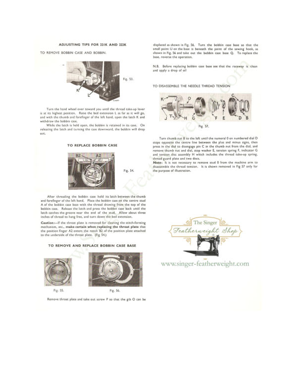
Singer 221 & 222 (Featherweight) Service Addendum
Service manual
6 pages · EnglishRead →
SingerPDF
Singer 221 (Featherweight) Adjusters
Service manual
20 pages · EnglishRead →
From the ISMACS International. Original publisher and archive notices are retained.
Check the model and edition against your equipment.
PDF verified 2026-10-11.