Sewing machines
Singer 201-1, 201-2, 201-3, 201-4, & 1200-1 Adjuster's — Service manual
Service manual for Singer 201-1, 201-2, 201-3, 201-4, & 1200-1 Adjuster's. 72 pages in English. Read the original PDF, download or print a copy without registration.
72 pagesEnglish6.0 MB PDF
Loading your manual…Open PDF directly
Document details
- Brand
- Singer
- Model / document
- Singer 201-1, 201-2, 201-3, 201-4, & 1200-1 Adjuster's
- Document type
- Service manual
- Language
- English
- Pages
- 72
- File size
- 6.0 MB
- Category
- Sewing machines
- Document date
- Not specified in catalog
Search available document text
Find a term, then jump to its page in the original PDF. Image-only pages may not be searchable; check the PDF for exact wording and diagrams.
Page 1 · Read text
Form 18962
(1236)
 ADJUSTER'S MANUAL
             FOR
  SINGER MACHINES
 201-1, 201-2, 201-3, 201-4
       AND 1200-1
     LOCK STITCH   REVERSIBLE FEED
             FOR FAMILY USE

   SINGER P. H. MOTORS
                   AND
   SINGER B. R. MOTORS
       AND BAKELITE CONTROLLERS

      SINGER


     SEWING

    MACHES


ThE SINGER MANUFACTURIng Co.

                           PRINTED IN U.S. A
View original page 1Page 2 · Read text
To all whom it may concern:
  The placing or renewal of the name "Singer" (Reg. U.S.
 Pat. Off.) or any of the trade marks of The Singer Manu-
 facturing Company on any machine that has been repaired,
 rebuilt, reconditioned or altered in any way whatsoever
 outside a Singer factory or an authorized Singer agency
is forbidden.


             Purchasing of Parts and Needles
    Supplies of parts and needles for Singer machines can be pur-
 chased at any Singer Shop or ordered by mail. If orders are
 sent by mail, money or a post office order covering their value,
 including postage, should be enclosed and the order will then be
 promptly filled and forwarded by mail or express.


               Genuine Singer Needles should be used
                         in Singer Machines.
                These Needles and their Containers
                       are marked with the
               Company's Trade Mark "SIMANCO." 1


                    Needles in Containers marked
                     "For Singer Machines"
                     are not Singer made needles.


       Copyright, U.S. A., 1021, 1031, 1932, 1935 and 1936, by The Singer Manufacturing Co.

                                All Rights Reserved for all Countries
View original page 2Page 3 · Read text
F'our 18963


 ADIUSTER'S MANUAL
              FOR
   SINGER MACHINES
  201-1, 201-2, 201-3, 201-4
     AND 1200-1
     LOCK STITCH    REVERSIBLE FEED
              FOR FAMILY USE

   SINGER P. H. MOTORS
               AND
   SINGER B. R. MOTORS
         AND BAKELITE CONTROLLERS


                                 SINGER


                      MACHINE 201-2


 THE SINGER MANUFACTURING CO.
View original page 3Page 4 · Read text
2
           INDEX
                                                    PAGE
ARM SHAFT
     TO REMOVE AND REPLACE HORIZONTAL ARM SHAFT, HORIZONTAL
     ARM SHAFT BUSHINg, HORIZONTAL ARM SHaFT GEaR AND
      COUNTERBALANCED FEED CAM AND FEED LIFTING ECCENtRIC..62-66
     TO REMOVE AND REPLACE UPRIGHT ARM SHAFT AND I PRIGHT
      ArM SHaFT GEaRS                                      61, 62
BALANCE WIIEEL
     TO REMOVE AND REPLACE BALaNcE WHEEL (MACHINE 201-2)..    26
     TO DISASSEMBLE AND REASSEMBLE BALANCE WHEEL (MICH. 201-2) 27, 28

BELT
     TO ADJUST BELT TENSION (MACHINE 201-3             36
BOBBIN CASE
       To REMOVE AND REPLACE                           42

BOBBIN WINDER
       To ADJUST                                     54
BAKELITE CONTROLLERS-FOR MACHINES 201-2 AND 201-3.    37-41
      APPLICATION OF CONVERTIBLE FOOT AND KNEE CONTROLLER TO
        CABINET 48.                                                 ... 9,10
    EMERGENCY ADJUSTMENT OF CARBON RESISTANCE UNIT OF
          TREADLE, KNEE AND FOOT CONTROLLeRS.                    ... 38-40
DESCRIPTIONS OF MACHINES                4

ELECTRICAL CONNECTIONS-FOR MACHINEs 201-2 AND 201-3   6- 8
       TO INSPECT ELECTRICAI. CONNECTIONS (MACHINE 201-2        13-25
      TO INSPECT ELECTRICAL CONNECTIONS (MACHINE 201-3)       28-36

 FEEDING MECHANISM
     FEED CONNECTING ROD--To REMOVE AND REPLACE           57-59
      FEED DOG-To REMOVE AND REPLACE                    42
        TO RAISE OR LOWER..                           50
         TO ADJUST LENGTHWISE IN THROAT PLATE SLOTS           50
         TO ADJUST CENTRALLY IN THROAT PLATE SLOTS            51

FEED FORKED CONNECTION AND FEED REGULATOR
      To REMOVE AND REPLACE                              59.60
PRESSER BAR-To AdJUST….                            55
       To REMOVE AND REPLACE                           55

LUBRICATION
      TO LUBRICATE THE MOTOR (MACHINE 201-2)               26
      TO LUBRICATE THE MOTOR (MACHINE 201-3'                36
       To OIL THE MACHINE                                        67, 68
View original page 4Page 5 · Read text
3

                  INDEX-Continued
                                                 PAGE
HOTORS
       ('ARSES OF ISPORRECT SPEED OR FAILTRE TO RES             11-13
       DESCRIPTION OF SIOTORS FOR SACTISE: 20122               3.      +- 6
     TO REMOVE MOTOR FROM MACHINE 201                  21
     TO REMOVE MOTOR FROM MACHINE 201
     TO DISISSEMBLE AND REISSEMBLE: MOTOR ( MACTINE 201 --2:    22-25
         DISASSEMBLE AND REASSEMBLE STOTORMACHINE 201-3    31 35
     TO REDLICE AloTOR ( ACHIS& 201
        REPLACE MOTOR ( MArTINE 201

POSITION PLATE
     TO REMOVE AND REPLACE                              +3
SINGERLIGHT
     TO REMONE AND REPLANCE SINGERLIGHT AND-SISAERLIGHT LEADi
        (MACHINE 201-2)                                 14-19
     TO DISSEMBLE AND REISSEMBLE SISGERLIGHT ( Alen. 201-21     15
            TO REMOrE AND REDLACE SINGERLIGHT ( lACINE 201-31       28-30
     TO DINASSEMBLE AND REASSEMBLE SINGERLIGHT • NH. 201 3:  29-30

STITCHING MECHANISI
      \geDLE BaR TO SET AT ('ORRECT HEIGHT                   16
          To REMOVE AND REPLICE                           56.57
     ROTATING HOOK- To TIME.                           44.45
          To REMOVE AND REPLACE.                          43
      ROTATING HOOK SHAFT AND ROTATING HOOK SHAFT (iEAR
          To REMOVE AND REPLACE.                                46, 47
      ROTATING HOOK DRIVING SHAFT AND ROTATINO MOOR DRINING
         SHAFT CIEARS
         To REMOVEAND REPLNE.                          17-49

THREAD CONTROL MECHANISM
      SEEDLE THREAD TENSION---TO REMOVE
     TO REISSEMBLE IND REPLACE                              52-54
View original page 5Page 6 · Read text
DESCRIPTIONS
    All of the Class 201 lock stitch. adjustable reverse feed Ma-
 chines for family use are equipped with a horizontal rotating
 sewing hook which makes two revolutions to each stroke of the
 needle bar. The rotating sewing hook takes the loop from the
       left side of the needle, thus forming a perfeet stitch in both
 forward and reverse directions.
    These machines are all equipped with a feed throw-out device
 by means of which the feed dog can be lowered, when desired, so
that the feed dog teeth do not project above the top surface of
 the throat plate.
 They are all equipped with thread tension having a graduated
 scale for accurately and conveniently adjusting the needle thread
tension.
    They are all equipped with a hinged presser foot.


   Machine 201-1 is equipped for foot power operation only on
a treadle stand.
   Machine 201-2 is motor driven through gears, having the
 Singer P. H. Motor built on the back of its arm, and is equipped
 with Singer Carbon Controller.
   Machine 201-3 is motor driven through a bell. being
 equipped with Singer B. R. Motor and Singer Carbon Controller.
   Machine 201-4 is equipped for hand operation only.
   Machine 1200-1 is the same as Machine 201-2, except that
it is equipped with knee lifter for raising the presser foot.


          Motors for Machines 201-2 and 201-3
    These motors are operated on either alternating current or
 direct current. but the motor rating must be selected to corres-
 pond with the electric current available. Therefore, betore con-
 necting the motor to the electric service line, check the data
 stamped on the motor name plate with the local Electric Com-
 pany to make sure that the volts and cycles agree.
      C'arefull observe these instructions when selecting the motor
 from the lists on the following page
View original page 6Page 7 · Read text
Singer P. H. Motors for Machine 201-2
    The Singer P. H. Motors, which are built on the No. 201-2
 Machine, are listed next below:


                           Direet Current
                        und 25 10 75 Civeles
                             .Alternatino Current


                       80 to 100 Creles
                           Alternatmno ( urrent


          Singer B. R. Motors for Machine 201-3

    The Singer B. R. Motors for Machine 201-3 are listed next.
below:


                         Direct Current Onl


                             Direct Current
                        and 23 10 75 l'vele
                           alternating Current

130. 14;

                          Alternating Current              K. 92

   Only rarely is a supply of electricity found where none of the
motors listed is suitable. In such cases, the factory should be
consulted regarding the possibility of supplying a special motor.
View original page 7Page 8 · Read text
6

     To Insure Correct Demonstration of Machine
  Be sure that the voltage range specified on the motor name
plate is within the range of voltage of the electric service line.
A higher service line voltage will produce excessive speed
and will cause damage to the motor, while a lower voltage
will cause the motor to operate too slowly.

               IMPORTANT
   Before operating the machine, see that it and the motor are
properly lubricated.
  See "To Lubricate the Motor," pages 26 and 36, and "To Oil
the Machine." pages 67 and 68.

    Electrical Connections for Machines 201-2 and 201-3
   The pins of the three-pin terminal are numbered 1, 2 and 3.
The numbers 1 and 3 are vellow and red respectively, while pin
number 2 is uncolored.
   For Machine 201-2, the leads from the Singerlight for pins
1 and 3 have tracer threads of corresponding colors running
through them.
   For Machine 201-3, the leads from Singerlight for pins 1 and
  3 have vellow and red identification tubing respectively.
 For both machines -One of the controller leads has vellow
identification tubing, while the lead for attachment to the tin-
colored pin, No. 2, is without identification tubing. One of the
motor leads has red identification tubing, while the lead for
 attachment to the uncolored pin No. 2, is without identificaticn
tubing.
  The lead cord for the power supply is provided with a plug
for the electric outlet: also a plug for the three-pin terminal. The
 three-pin terminal plug is marked with the numerals 1, 2 and 3
 to correspond with the pin numbers of the three-pin terminal.
 The power leads are connected to terminals 1 and 3 of the three-
pin terminal plug. These two wires are knotted together as shown
 in Figs. 13 and 14.
   The switch for the Singerlight with which Machine 201-2 is
equipped is housed in the three-pin terminal.
   The switch for the Singerlight for Machine 201-3 is integral
 with the Singerlight.
View original page 8Page 9 · Read text
The connections are made as follows:
          Machine 201-2, Singer P. H. Motor,
                 Singerlight and Controller

                        (SEE FIG. 2, WIRING DIAGRAM)
    Motor Leads Fasten the lead with the red identification
  tubing to the red pin No. 3. and fasten the lead without identi-
    fication tubing, to the middle pin No. 2, as illustrated in Fig. 2.


                              Singerlight
                   Yellow.         Black
                                 -Red
         Three
            Pin
           Terminal                                     " To Motor

                                     Black
               Yellow

                    White

                FlOw
                                  Leads Tube Clamp
                   Black

                                                       Fia. 2
                                          WIRING DIAGRAM
                              Controller         THREE-PIN TERMINAL
                             Unit                 tO Aloror
                                          CONTROLLER AND
                                                 DISGERLIGI"
                                     MACHINE 201-2


   Singerlight Leads Fasten the lead with the yellow tracer
 thread to the yellow pin No. 1. The Singerlight white lead is
 attached to the screw connection of the Singerlight switch. The
 short red lead which is soldered to the Singerlight switch, shou'd
be fastened to the red pin No. 3.
   Controller Leads Fasten the lead with the yellow identi-
 fication tubing to the yellow pin No. 1, and fasten the lead
 without identification tubing to the middle pin No.
View original page 9Page 10 · Read text
Machine 201-3, Singer B. R. Motor,
              Singerlight and Controller

                  (NeE Pre. 3. WIRING DIAGRAM)
  Motor Leads Fasten the lead with the red identification
tubing to the red pin No. 3, and fasten the lead without identi-
 fication tubing to the middle pin No. 2, as illustrated in Fig. 3.


                                               Singerlight

                          Black
                Yellow           Red


                                    Three Pin
                                       Terminal

                   Yellow           Red
             Red        Black To Motor
                   Yellow.

                            Black                                               FiG. 3
                                            MIRING DIAGRAM
                                        THREE- PIN TERMINAL

                                        CONTROLLER AND
                                                 SINGERLISITT
                                      MACHINE ZO13

        | Controller Unit


    Singerlight Leads Fasten the lead with the yellow identi-
fication tubing to the yellow pin No. 1, and fasten the lead with
the red identification tubing to the red pin No. 3.
   Controller Leads Fasten the lead with the yellow identi-
   fication tubing to the yellow pin No. 1, and fasten the lead
without identification tubing to the middle pin No. 2.
View original page 10Page 11 · Read text
INSTRUCTIONS FOR USING THE
   BAKELITE CONTROLLER FOR FOOT OR KNEE
        OPERATION WITH CABINET 48

   For instructions covering the care and adjustment of
the Bakelite Treadle Controller and Convertible Foot and
Knee Controller, see pages 37 to 41 inclusive.


           When Used for Foot Control
   Slide the controller downward out of the holder B and place
it on the floor in a position convenient for the operator, then turn
up the knee lever As as shown in Fig. 4.


                            ASTROLLER ARRANGED FOR
View original page 11Page 12 · Read text
When Used for Knee Control


  Insert the controller upward
 intothe holder ‹B)withthe pedal
(E) toward vou and the base of
 the controller in the side guides
 (Ch. Push up the controller un-
 til it rests against the stops D1,
only one of which is visible in
Fig. 5.


                                              PIG. 5. PLACING BAKELITE: CON-
                                   TROLLER IS CABINET 48
                                    FOR ANEE CONTROL


                                   Place the slack controller lead
                                to the rear on the shelf of the
                                    cabinet, asshown at (H) in Fig. 6,
                          no hook being required to hold
                              the slack lead.
                                Turn down the knee lever (A).
                             Loosen the thumb screw (G) and
                         move the knee lever to the right
                 22.34.                    or left to bring the knee lever
                            (A) to the position best suited
     PIG.            6. BAKELITE                CONTROLLER
    ARRASGED             FOR                 ASEE CON-       for the operator, then tighten
                                  the thumb screw (Ci).
View original page 12Page 13 · Read text
CAUSES OF TROUBLE WITH MACHINES OF CLASS 201
   Machines of Class 201 may fail to run properly due to damage
after final factory inspection.
   Machines 201-2 and 201-3 might fail to start or might run
100 fast or too slowl due to such damage or to improper selec-
tion of motors.
   Trouble with an of the Class 201 Machines might also be
due to the following causes:
         Causes of Low Speed or Failure to Run
    1. Heavy or Gummed Lubricant. If the sewing machine
has not been run for some time, the lubricant may have become
heavy, thereby reducing normal speed and, in the case of Ma-
chines 201-1 and 201-4, making undue effort necessary for its
operation. To overcome this, run the machine unthreaded for
a few minutes with the presser foot raised. If a poor grade of
lubricant has been used and has become gummy, wash off all
of the lubricant from the sewing machine with kerosene, dry
with a clean cloth and re-lubricate with Singer oil
   2. Too Much Presser Foot Pressure. Pressure should be
as light as possible with positive feeding of the material.
    3. Machine Binds. Determine this by rotating the balance
wheel slowly, by hand, in the direction for sewing. If the ma-
chine binds, do not run it until all of the working parts have
been inspected and any defects corrected. By disconnecting the
lower end of the feed connecting rod from the feed lifting rock
shaft, also the lower end of the feed forked connection from the
feed rock shaft, it will be easy to determine whether binding
occurs in the arm or in the bed of the machine. See pages 57 to
60. which cover the removal and replacement of the leed con-
necting rod and the feed forked connection. Also bear in mind
that a dry machine will bind and should be lubricated with
Singer oil.
     MOTOR CAUSES OF TROUBLE WITH
          MACHINES 201-2 AND 201-3
   4. Electric Current Not Turned On.
   5. Loose or Broken Electrical Connections. Examine
carefully all plugs and connections (Machine 201-2) on pages 13
     to 25 inclusive. or (Machine 201-3) on pages 28 to 36 inclusive,
and make sure that there are no broken wires and that all screwed
and soldered connections are tight.
    If the pins of the three-pin terminal fit loosely in the three-
pin terminal plug, slightly spread apart the prongs of the pins.
These pins (C4) are shown in connection with Machine 201-2
View original page 13Page 14 · Read text
in Figs. 7 and 15, pages 13 and 21: also in connection with Ma-
chine 201-3 in Fig. 22. page 31.
    6. Motor Not Suited for Electric Supply. Make sure that
the volts and cycles, stamped on the name plate of the motor,
agree with the electric current available. If the motor is run on
 a voltage lower than that stamped on the name plate, the speed
of the motor will be too slow. If the motor is run on a voltage
higher than that stamped on the name plate. the speed of the motor
will be too fast and cause damage. See "Motors for Machines
201-2 and 201-3," pages 4. 5 and 6.
    7. Dirty Commutator. See that there is no carbon or grease
Cleanon thethecommutator.Armature" ( andMachinethat it201-2)is smooth.pages 22Seeand"Inspect23. or (Ma-and
chine 201-3) pages 32 and 33
    8. Carbon Brushes Not Making Contact. This may be
 due to brushes sticking in the brush tubes, or to grease on the
commutator. See "Clean Brushes and Brush Tubes* | Machine
201-2) page 23. or (Machine 201-3) page 331. See also "Remove
Brushes' (Machine 201-2) page 22. or Machine 201-3) page 32
and "Replace Brushes" (Machine 201-2 page 25, or (Machine
  201-3) page 35.
    9. Armature Binding. To determine whether or not the
 armature binds, proceed as instructed under lat or b) following:
     (r). Machine 201-2. Remove the motor cover as instructed
       on page 22, then, to disengage the motor from the bal-
        ance wheel, remove the balance wheel as instructed on
        page 26. The removal of the motor cover exposes the free
         endof the armature. With the fingertipsrotate the armature.
     (b). Machine 201-3. Remove the belt from the motor pulley
         and, by means of the pulley, rotate the armature by hand.

    Causes of Binding:
        Machines 201-2 and 201-3
    18). Grease wicks and tubes may be dry. See lubricating
         instructions on pages 26 and 36 respectively.
      (d). Armature striking field ccils.
      (el. Foreign substances in the armature shaft bearings.
        Grease wicks must be removed from the shalt bearings
        before replacement of the armature shalt. See "Replace
        Armature" (Machine 201-2) pages 21 and 25, or "Replace
        Armature' Machine 201-3) page 34, and "Replace Pul-
         ley End Cover" (Machine 201-3) page 35.
            ) The armature shaft may be bent. If so, the armature
         should be replaced.
View original page 14Page 15 · Read text
Machine 201-2 Only
    l4 Brush lubes rubbing on the commutator. This might
        occur with the brush tubes not properly positioned in the
        insulating bushings. See "Remove and Replace Brush
        Tubes," page 23.
       Machine 201-3 Only
     this Alotor and covers not properly sealed and tightened. See
        "'Replace Commutator End Cover," page 34, and "Re
        place Pulley End Cover," page 35.
    10. Broken Armature Wires. See that the fine wiring on
the and of the armature is not broken. See "Inspect and Clean
the Armature" (Machine 201-2) pages 22 and 23. or (Machine
201-3) pages 32 and 33.
    11. Controller Not Properly Adjusted. See instructions
(Machine 201-2) and (Machine 201-3) on pages 37 lo 41 inclusive.

     TO INSPECT ELECTRICAL CONNECTIONS
                  Machine 201-2
   Three-Pin Terminal. Remove the screw (A4, Fig. 7) to
displace the three-pin terminal (B4) from its bracket (V4) on the
                                   machine arm. While the
                              the removal ol the
                               three-pin terminal
                               bracket (V4) is not
                     _V4          essential, it is recon-
                                 mended when inspect-
                     -A4      ing the connections at
                     B4      the three-pin terminal
                                         This bracket is removed
                                  by taking out the screw
                                          at (F13. Fig. 10).
                    C4                                         Inspect the connec-
                                             tions at the three thumb
        IN TENCE ON ALICINE 201           nuts (Q4. Fig. 10). See
                                         that they are screwed
 down firmly to insure tight connections. Each of the three pins
is provided with a washer. See that this washer is, in each case,
 placed above the wire or wires before tightening the thumb nuts
 (04, Fig. 10).
View original page 15Page 16 · Read text
14
   Motor- Machine 201-2. To inspect the connections in the
motor, remove the motor from the machine as instructed on page 21.
   Inspect the soldered connections (R. Fig. 17) at the brush tubes.
   See "Replace Field Core with Coils," page 23.
     Replace the motor as instructed on page 225.
    Singerlight Machine 201-2. To inspect the Singerlight
connections, it is not necessary to disconnect the Singerlight leads
from the three-pin terminal, nor is it necessary to remove tic
                DA       E4


                        F4             M
                        G4
                     H4


         LA
                KA-A
                          270697

            FO. S. SINGERLIOnS REMOVED FRONT MACHINE: 201-2

leads from the machine arm. It is necessary, however, to remove
 the complete Singerlight from the machine as shown in Fig.
8. by removing the screw at (M4, Fig. 8), after which the Singer-
 light can be disassembled as follows:
  Remove Singerlight Shade - Machine 201-2. With the
Singerlight removed as shown in Fig. 8, remove the screw (J4)
which fastens the Singerlight socket (Y4. Fig. 9) in the base of
the Singerlight shade (K4), and loosen the screw (H4) which
retains the leads tube at its upper end (F4) in the entrance (G4)
of the Singerlight shade. The Singerlight shade (K4) is then
 easily slipped from the upper end of the leads tube and the lamp
socket by withdrawing the shade to the right.
View original page 16Page 17 · Read text
Inspect Singerlight Connections- Machine 201-2. With
the Singerlight shade removed as instructed on the preceding page.
take out the two screws (BS, Fig. 9) which fasten the Singerlight
socket cap (AS) to the socket body. Carefully inspect. the two
 soldered connections (F5) to make sure that they are tight.
  Reassemble the Singerlight Machine 201-2. Reverse the
foregoing instructions for disassembling, making certain that the
ray (A5) is seated firmly on the lamp socket (Y4), then insert
 and tighten the two screws (BS) through the holes (D5) in the

  E5
            24
              F4
               A5       W4

           F'5  Y4
                     -C5
                            G5
         D5                           H5            B5


                 Ire. 9.FINGEREROUS DISASSEMBLED
                 REMOVED FROM NIACHINE 201

cap and into the holes (Es) in the lamp socket body. Put the
felt washer (Co) on the cap (A5) and put the assembled lamp
 socket in place in the Singerlight shade base with the upper end
(F4) of the leads tube in the entrance (G4, Fig. 8) of the shade,
and with the fibre clamping plate (Z4) in place against the upper
end (F4) of the leads tube where the set screw (H4, Fig. 8) will
he tightened against it. Insert and tighten the screw (14, Fig. 8),
 thus fastening the lamp socket (Y4) into the base of the shade
(K4. Fig. &) and carefully tighten the set screw (H4, Fig. 8)
  against the fibre clamping plate (74).
   Replace Singerlight-Machine 201-2. Attach the cont-
 pletely assembled Singerlight to the machine arm, having the
two pins (I4. Fig. 8) in the holes (D4, Fig. S). Tighten the
screw at (NI4, Fig. 8).
View original page 17Page 18 · Read text
To Remove Singerlight Leads from the Machine Arm
                     Machine 201-2
   Remove the Three-Pin Terminal as instructed on page 13.
    Disconnect the vellow Singerlight lead from Pin No. 1 of the
 three-pin terminal, and disconnect, a Pin No. 3, the red lead
 which is soldered to the Singerlight switch Ta. Fig. 10).

                                            Fi3
            VA


           U4                 N5
                         H5
                                         -04
                             P4
         S4.
       T4             N4

        B4
                        04

        DIG. 10. THREE-PIN TERMINAL DISPENCED PRON MENCHINE ARM
        SHOWING CONNECTIONS AT THREE-PIN TERMINAL AND SNITCH
                         (MACHINE 201-2)

   Remove the knurled thumb nut (S4) and the hexagon lock
 nut (U4) from the serew nipple of the Singerlight switch (74).
Then carefully push the entire switch, including the switch
handle, back into the switch housing (4), and lift the entire
 switch (T4) from the housing (4) with the Singerlight white
lead and the short red lead attached. With the switch (T4)
 removed from the housing (P4), the screw connection (4) and
the soldered connection (R4) are accessible. Remove the screw
(V4) and disconnect the Singerlight white lead from the switch (1'4).
   Remove the Singerlight from the machine as instructed an
page 14
View original page 18Page 19 · Read text
17

      Loosen set screw (O4. Fig. 10) to release the clamp (H5, Figs.
     " and 101 which holds the three-pin terminal end of the leads
    tube (A4. Fig. 11) containing the Singerlight leads.
                                 Before removing the
                                   Singerlight leads from
                                       the machine arm, be sure
       X.                               to observe the position of
                                        the leads tube (W4) in the
                              machine arm, so that it
                                    will be replaced in the
                             same position as before
                                removal.;E                        The position of the tube
                                   11) can be observed con-
                                          venientiv through the open-
                                      ing (X4) uncovered by the
                                  removal ol the stitch indi-
                                    cator plate. This plate is
                               removed by taking out the
                             two screws by which it is
   W4                          fastened to the machine
                                 arm. The lower and of the
                                   lube (I'4) can be observed
                                    through the opening (K5,
            FIG.                    IL. STITCH                      INDICATOR                                  PASTE:    Fix. 12) in the bed of the            REMOVED                     TO                       SRON ATE POSETIOS
                                  machine.
            ARM OF MINITENNE 201          The Singerlight shade may
                                  be removed either now or
                                               after the removal of the leads
    tube (I'4) from the machine arm. The shade is removed as in-
     structed in the last paragraph of page 14.
      Wichdraw the tube (W4) from the machine arm through the
    opening (I, Fig. S), together with the clamp (Ho, Figs. 9 and 10),
     or remove the clamo (H5) separately from the tube through the
   opening (KS. Fie. 12) in the machine bed.
     Should it be necessary to disassemble the Singerlight, follow
    the instructions under "Inspect Singerlight Connections." page
    1s. and reassemble the Singerlight as instructed on page 15
       Replace the Singerlight leads as instructed on pages 18 and 19.
View original page 19Page 20 · Read text
18
           To Replace the Singerlight Leads
                   Machine 201-2
   With the Singerlight completely disassembled, as shown in
 Fig. 9, insert the tube (W4, Figs. 9 and 12) with the clamp (Ho.
          Figs. 9 and 12) in place thereon, into the Singerlight seat opening

                        L5W4H5
                         VA


                            M5
                                  JE


     K5                                      E11696
             110. 12. SHOWINe POSITION OF THE SINGERLIEr LEADS
            VIEN THROCON THE OPENING IN THE MINCITINE: BED
                        (MACHINE 201-2)
(E4, Fig. 8) in the machine arm, and move the tube (14) con-
taining the Singerlight leads back toward the balance wheel
  at the same time keeping the tube (W4) at the front side (toward
 the operator) of the horizontal arm shalt in the machine arm;
then, reaching through the opening (X4, Fig. 11), guide the lube
  (4) downward while keeping this tube at the tront side (toward
the operator) of the upright arm shaft as shown in Fig. 11. While
guiding the tube (W'4) downward toward the leads opening at
 the three-pin terminal seat, keep this tube to the left of the feed
connecting rod (L5, Fig. 12). From this point downward, the
 tube (WI) is guided by reaching through the opening (Kö) in
the machine bed. Guide the tube (W4) downward and to the
View original page 20Related documents and language editions

SingerPDF
Singer 101-1
Parts list
42 pages · EnglishRead →
SingerPDF
Singer 101-1, 101-2, 101-3, 101-10, & 101-11 Adjusters
Service manual
48 pages · EnglishRead →
SingerPDF
Singer 101-2, 101-3, 101-10 & 101-11
Parts list
136 pages · EnglishRead →
SingerPDF
Singer 101-3 & 101-11 Adjuster's
Service manual
20 pages · EnglishRead →
SingerPDF
Singer 115-1 & 115-2 Parts List
Parts list
38 pages · EnglishRead →
SingerPDF
Singer 128-8 Parts List
Parts list
20 pages · EnglishRead →

SingerPDF
Singer 15-86 & 15-87 Parts List
Parts list
61 pages · EnglishRead →

SingerPDF
Singer 15-88, 15-89, & 15-90 Parts List
Parts list
63 pages · EnglishRead →

SingerPDF
Singer 206K25 Service
Service manual
28 pages · EnglishRead →
SingerPDF
Singer 206K25, 206K43, 306, 319, and 401 Service
Service manual
174 pages · EnglishRead →
SingerPDF
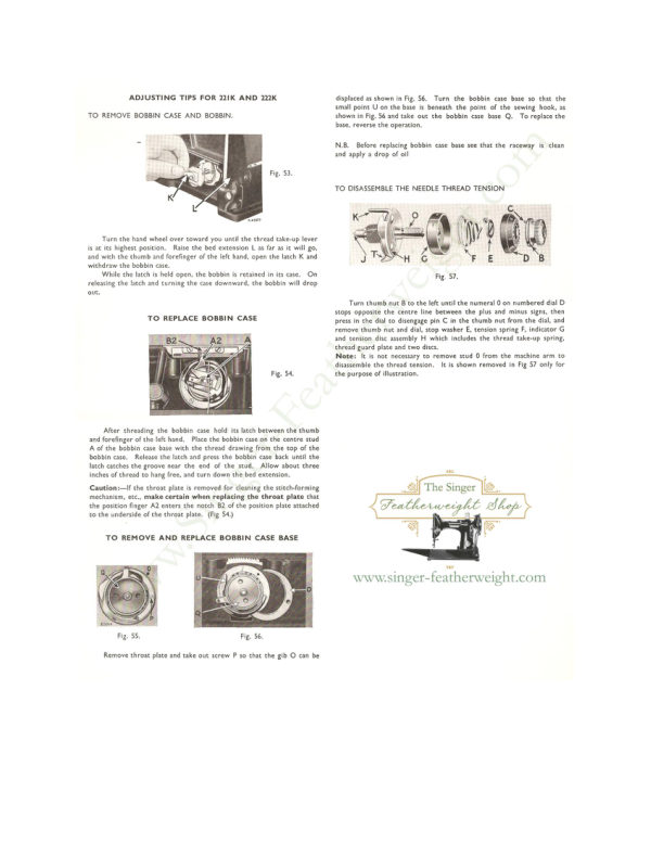
Singer 221 & 222 (Featherweight) Service Addendum
Service manual
6 pages · EnglishRead →
SingerPDF
Singer 221 (Featherweight) Adjusters
Service manual
20 pages · EnglishRead →
From the ISMACS International. Original publisher and archive notices are retained.
Check the model and edition against your equipment.
PDF verified 2026-10-11.