Sewing machines
Singer 221 & 222 (Featherweight) Service Addendum — Service manual
Service manual for Singer 221 & 222 (Featherweight) Service Addendum. 6 pages in English. Read the original PDF, download or print a copy without registration.
6 pagesEnglish3.3 MB PDF
Loading your manual…Open PDF directly
Document details
- Brand
- Singer
- Model / document
- Singer 221 & 222 (Featherweight) Service Addendum
- Document type
- Service manual
- Language
- English
- Pages
- 6
- File size
- 3.3 MB
- Category
- Sewing machines
- Document date
- Not specified in catalog
Search available document text
Find a term, then jump to its page in the original PDF. Image-only pages may not be searchable; check the PDF for exact wording and diagrams.
Page 1 · Read text
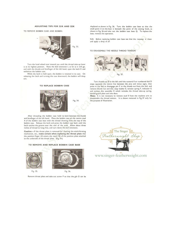
ADJUSTING TIPS FOR 22IK AND 222K               displaced as shown in Fig. 56. Turn the bobbin case base so that the
                                                                        small point U on the base is beneath the point of the sewing hook, as
TO REMOVE BOBBIN CASE AND BOBBIN.                        shown in Fig. 56 and take out the bobbin case base Q. To replace the
                                                                      base, reverse the operation.


                                                                      N.B. Before replacing bobbin case base see that the raceway is clean
                                                             and apply a drop of oil

                                              Fig. 53.

                                                   TO DISASSEMBLE THE NEEDLE THREAD TENSION


     Turn the hand wheel over toward you until the thread take-up lever
 is at its highest position. Raise the bed extension L as far as it will go,
and wich che chumb and Toreringer or the lerc hand, open che laccn a and
 withdraw the bobbin case.
     While the latch is held open, the bobbin is retained in its case. On                                Fig. 57.
releasing the latch and turning the case downward, the bobbin will drop
OUt
                                                                         Turn thumb nut B to the left until the numeral 0 on numbered dial C
                                                                            stops opposite the centre line between the plus and minus signs, then
           TO REPLACE BOBBIN CASE                         press in the dial to disengage pin C in the thumb nut from the dial, and
                                                             remove thumb nut and dial, stop washer E, tension spring F, indicator (
           B2                                     and tension disc assembly - which includes the thread take-ud spring
                                                                            thread guard plate and two discs.
                                                                    Note: It is not necessary to remove stud 0 from the machine arm to
                                                                 disassemble the thread tension. It is shown removed in Fig 57 only for
                                                      Fig, 54.            the purpose of illustration.


      After threading the bobbin case hold its latch between the thumb
 and forefinger of the left hand. Place the bobbin case on the centre stud
 A of the bobbin case base with the thread drawing from the top of the
 bobbin case. Release the latch and press the bobbin case back until the
latch catches the groove near the end of the stud. Allow about three
  inches of thread to hang free, and turn down the bed extension.
 Caution: If the throat plate is removed for cleaning the stitch-forming           * The Singer
 mechanism, etc., make certain when replacing the throat plate that
 the position finger A2 enters the notch B2 of the position plate attached                                      Featherweight Shop
  to the underside of the throat plate. (Fig 54.)


   TO REMOVE AND REPLACE BOBBIN CASE BASE


                                       www.singer-featherweight.com


          Fig. 55.                             Fig. 56.


    Remove throat plate and take out screw P so that the gib O can be
View original page 1Page 2 · Read text
TO TIME THE ROTARY SEWING HOOK (221 K)                  TO SET THE NEEDLE BAR AT THE CORRECT HEIGHT

    Remove the face plate, presser foot, throat plate and feed dog.
 Place a new needle in the needle bar, pushing it up into the needle bar as           With the hook correctly timed, as instructed on page 25a, turn the
                                       far as it will go. The       balance wheel toward you until the needle bar reaches its lowest point.
                                          needle bar has two timing                                        With the needle bar in
                                          marks near its upper end.                                                          this position, the upper
                                        Turn the balance wheel                                                 timing mark should be
                                  toward you until the                                            centred with the lower
                                   lower timing mark on                                    end of the needle bar
                                            the needle bar is centred                                            bushing as shown at (F,
                                                with the lower end of the                                                      Fig. 117). If the needle
                                            needle bar bushing when                                      bar is not set at the
                                         the needle bar is on its                                                 correct height, loosen
                                     upward stroke, as shown                                          screw (D, Fig. 117) and
                                                                                     move the needle bar up                                              at (X, Fig. 115). When
                                        the needle bar is in this                                                   or down until the upper
                                                   position, the point of the                                                timing mark is centred
                                    sewing hook should be                                                   with the lower end of the
                                    at the centre of the                                            needle bar bushing as
                                         needle, as shown at (Z,                                     shown at (F, Fig. 117).
                                                                              Fig. 117. Needle Bar Set at Correct Height. Then securely tighten
                                                 Fig. 115), if the hook is
                                     correctly timed.                                             screw (D).
                                                                   The needle bar bushing is accurately set at the factory, and its position
                                     case the hook is not
                                                                    should not be disturbed. If its position has been disturbed, turn the
                                                 correctly timed, turn the        balance wheel toward you until the point of the hook is at the centre of
                                            machine over on its rear
                                                                                  the needle and approximately , inch above the top of the eye of the needle.
                                              side and remove the bot-
                              tom cover plate after       Loosen set screw (W, Fig. 115) and move the bushing up or down until
                                                                                                         its lower end centres with the lower timing mark at (X, Fig. 115). Then
                                              taking off the thumb nut
                                                                                 tighten set screw (W, Fig. 115).
                                       which holds the bottom
                                    cover plate in place.
                                        Loosen the two set screws
  Fig. 115. Timing Rotary Sewing Hook.     in the gear on the right
                               hand end of the hook    TO ADJUST THE POSITION OF THE FEED DOG LENGTHWISE IN
                                                       THE FEED DOG SLOTS IN THE THROAT PLATE
 shaft, and turn the hook until its point is in proper relation to the
 needle as explained above. Then tighten the two screws (C, Fig. 116),
                                                                The feed dog should be positioned in the slots of the throat plate so
 making sure that the gear is pushed against the bushing at the right
                                                                                  that it will not come in contact with the throat plate at either end of the
hand end of the shaft, and that the slightly raised portion or "boss",
                                                                                        slots during its travel. If the feed dog is not correctly positioned, remove
 on one side of the collar and counterbalance is against the bushing
                                                                           the bottom cover plate. Loosen the nut (A, Fig. |16) on the end of the
  to prevent end play.
                                                                                eccentric screw, (B, rig. 116) and turn the screw so that the centre row of
 TO RAISE OR LOWER THE FEED DOG                                       teeth will be close to the end of the feed dog slot nearest the needle hole
                                                                                        in the throat plate, but not close enough to strike the end of the slot.
    When the feed dog is raised to its highest point by the feed con-       The eccentric screw (B, Fig. 116) is in correct position when the high throw
 necting rod, the top of the teeth should be not more than ¿ inch above        of the eccentric is upward and away from the gear (C, Fig. 116) on the
                               the top surface of the throat      hook shaft.
                                          plate. At this height, slightly less
                                 than the full depth of the teeth
                                               will protrude from the feed dog
                                        slots                                                in the                                                  throat                                                           plate.
                              When                                                                                           it                                                                 is necessary                                                                      to raise              The Singer
                                  or lower the feed dog, remove
                                      the bottom cover plate and loosen
                                    the nut (E, Fig. 116) on the end                            Featherweight Shop
                                          ot the feed lifting eccentric screw
                                    (D, Fig. 116). Turn the eccentric
                              screw (D) until the high throw
                                   of the eccentric is toward the
                                      rotary hook shaft gear (C, Fig.
                                    116). When the eccentric screw
    Fig. 116. Feed Dog Adjustment. (D) is in this position, the top of
                                   the feed dog teeth will be at the
 correct height above the throat plate. Be careful not to adjust the feed dog low enough to strike the hook when the feed is in reverse and when  www.singer-featherweight.com
  the longest stitch is being used. Then securely tighten nut (E, Fig. 116).
View original page 2Page 3 · Read text
OILING POINTS OF 221K                        OILING POINTS FOR THE SINGER 222K


                                                                                 Fig 16a.                             Fig. 17.                              Fig 16.

                                                                                            All moving parts in contact should be covered with a film of oil.       All moving parts in contact must be covered with a film of oil and not
                                                                 These must never be allowed to become dry.
 allowed to become dry. Oil should be applied at the points indicated by
                                                                                                                                 If used constantly, the machine should be oiled daily. A drop of oil the unlettered arrows in the above illustrations, a drop of oil being suffi-
                                                                        should be applied to each of the points indicated in figure 6a. Occasionally
 cient at any dlace.
     Turn back the cover at the top of the machine and oil the moving     apply a small quantity of Singer Lubricant for Electric Motors to the teett
                                                                                of the Gear A
 darts inside the arm as indicated, and occasionally addly a small quantity
 of Singer Motor Lubricant to the teeth of the gear (A), then replace the
cover. When oiling insert the oil can spout well into the oil holes.
  Occasionally apply a drop of oil at the hook bearing.


                                                X
                                                  Fig 14.


                                                                                         Fig. 18.                  Fig 19.

                                                          Remove face plate and put one drop of oil into each of the oil holes
                                                                 and joints arrowed as in Fig. 18.
                                                                          Occasionally apply a drop of oil at the hook bearing indicated by
                                                           "X " in Fig. 19.
    Take out the thumb screw and remove the face plate. Put one
drop of oil into each of the holes and joints indicated, then replace the
face plate and thumb scren


                                                     Fig 15.
                                                                                             Fig. 20.                         Fig. 21.

                                                                  Turn machine over on its rear side. Remove large cover plate
                                                               Take out screw and remove tubular bed cover.
                                                                                       Apply oil to the oil holes and bearings indicated in Fig. 20 and occa-
                                                                                      sionally apply a small quantity of Singer Lubricant to the gears "Z"
                                                             TO LUBRICATE THE MOTOR.
    Turn the machine over on its rear side, remove the thumb nut from      Use only Singer Lubricant. Apply the nozzle of the tube of grease
the screw t) and take oft the cover plate.Apply oil at the holes and    to points " A". This must be done at least every 6 months and more
  bearings indicated, and occasionally apply a small quantity of Singer Motor    trequently it the machine receives much use
 Lubricant to the teeth of the gears (D). Replace the bed cover plate and       The latest motors have self-lubricating bearings and DO NOT
  fasten it with the thumb nut, being careful not to turn the latter too tightly.   REQUIRE LUBRICATION.
View original page 3Related documents and language editions

SingerPDF
Singer 101-1
Parts list
42 pages · EnglishRead →
SingerPDF
Singer 101-1, 101-2, 101-3, 101-10, & 101-11 Adjusters
Service manual
48 pages · EnglishRead →
SingerPDF
Singer 101-2, 101-3, 101-10 & 101-11
Parts list
136 pages · EnglishRead →
SingerPDF
Singer 101-3 & 101-11 Adjuster's
Service manual
20 pages · EnglishRead →
SingerPDF
Singer 115-1 & 115-2 Parts List
Parts list
38 pages · EnglishRead →
SingerPDF
Singer 128-8 Parts List
Parts list
20 pages · EnglishRead →

SingerPDF
Singer 15-86 & 15-87 Parts List
Parts list
61 pages · EnglishRead →

SingerPDF
Singer 15-88, 15-89, & 15-90 Parts List
Parts list
63 pages · EnglishRead →
SingerPDF
Singer 201-1, 201-2, 201-3, 201-4, & 1200-1 Adjuster's
Service manual
72 pages · EnglishRead →

SingerPDF
Singer 206K25 Service
Service manual
28 pages · EnglishRead →
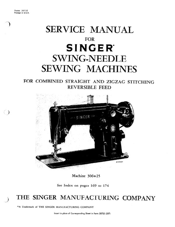
SingerPDF
Singer 206K25, 206K43, 306, 319, and 401 Service
Service manual
174 pages · EnglishRead →
SingerPDF
Singer 221 (Featherweight) Adjusters
Service manual
20 pages · EnglishRead →
From the ISMACS International. Original publisher and archive notices are retained.
Check the model and edition against your equipment.
PDF verified 2026-10-11.