Sewing machines
Singer 221 (Featherweight) Adjusters — Service manual
Service manual for Singer 221 (Featherweight) Adjusters. 20 pages in English. Read the original PDF, download or print a copy without registration.
20 pagesEnglish4.6 MB PDF
Loading your manual…Open PDF directly
Document details
- Brand
- Singer
- Model / document
- Singer 221 (Featherweight) Adjusters
- Document type
- Service manual
- Language
- English
- Pages
- 20
- File size
- 4.6 MB
- Category
- Sewing machines
- Document date
- Not specified in catalog
Search available document text
Find a term, then jump to its page in the original PDF. Image-only pages may not be searchable; check the PDF for exact wording and diagrams.
Page 1 · Read text
Form 18753
 March. 193

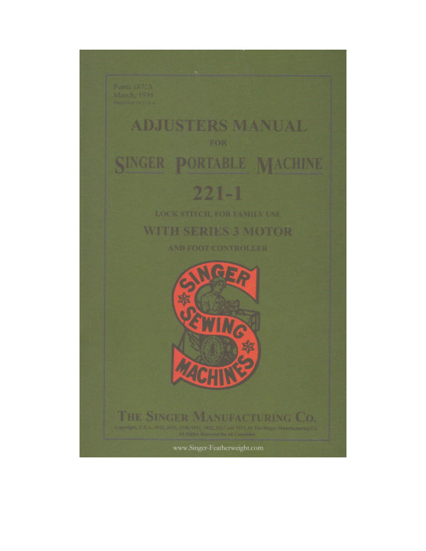
  ADJUSTERS MANUAL
              FOR

SINGER PORTABLE MACHINE
       221-1

       LOCK STITCH, FOR FAMILY USE
   WITH SERIES 3 MOTOR

          AND FOOT CONTROLLER

    ANGER

     SEWING


      CACHING


 ThE SingER MaNUfacturing Co.
        51. 884. 1921. 1329 7930.1031. 1932 1933


                    www.Singer-Featherweight.com
View original page 1Page 2 · Read text
rack Machine and Attach

   When placing the machine in its carrying case, have the bal-

ance wheel at the right hand side of the case and see that the base     machine is at the right of the cleat at the bottom of the ca         ADIUSTERS MANUAL

                                 SINGER PORTABLE MACHINE
                         221-1
                                              LOCK STITCH, FOR FAMILY USE
                            WITH SERIES 3 MOTOR
                                                AND FOOT CONTROLLER


  Heneeforth the attachments for Machine 221-1 will be shipped,
        • Metory.  1 a collapsible cardboard box. Singer Shops
                                     THE SINGER MANUFACTURING CO.
View original page 2Page 3 · Read text
INDEX                                               The Series 3 Motors. for use with3 MotorsMachine 221-1. are operated


                                                   Only rarely is a supply of electricity found where none of the
                                                   above listed motors is suitable. In such a case. the factors


                                               To Ensure Correct Demonstration of Machine

                                                        of the motor is within the range of voltase of the electre service

                                             speed and will cause damage to the motor, while a
View original page 3Page 4 · Read text
Flectricol Connections for Machine 221.


tinguished by a vellow and red spot, respectively, directly above

                                                                            Controller Leads Fasten the lead with the yellow trace
theonch them The sold bee

                                                                                 Electric Service Leads-
   Motor Leads- Fasten the lead with the red tracer thread to
                   .3. and fasten the solid black motor lead to the

    Singerlight Leads- -Fasten the lead with the yellow tracer
 thread to the vellow pin, No. 1, and fasten the lead with the red
View original page 4Page 5 · Read text
6. Motor Not Suited for Electric Supply     CAUSES OF TROUBLE WITH MACHINE 221-1
                                                                         See that the voltage of the electric supply, also the frequenc

                                                                                                             if it is alternating current, are within run on a
                                                                                    that stamped on the name pate tha speed of the motor will be
                                                                               too slow. If the motor is run on a voltage higher than that stamped
          Causes of Low Speed or Failure to Run                     on the name plate, the speed of the motor will be too fast

      it the sewir     chine has not                                          1. Dirty Commutator
       L mav have                                                   Dee that chere is no carbon or g
                                     it a poor bra                                      smooth.
 used and has become g                                                  Never use anything else on a small motor commutator.
 the sewing machine with kerosene,
re-lubricate with Singer Oil and Singer Motor Lubricant.

 2. Too Much Pressure on the Presser Foot


  • Machine Binds
                                                                                    This can be determined by rotating the motor pulley (B, Fig. 14)
      may   determined by turning over the balance wheel                with the fingers, when the belt is removed from the
                                      of the working parts
                 t the dame

                                        to fill the grease cups


 4. Electric Current Not Turned On
 5.- Loose or Broken Electrical Connections
   Damine carefully all plugs and connections in ac
with instructions on pages a to14, inclusive, and make sure
 that there are no broken wires and that all screwed and soldered
 connections are tight. If the pins of the three-pin terminal fit
loosely in the three-pin terminal plug, slightly spread apart the
View original page 5Page 6 · Read text
To Inspect Electrical Connections of Three-Pin Terminal
                   1gerlight and Singerlight Switch


remove bottom cover plate. ov


nal
[Brio a See that thethumb

          tight co

          pins is provided with


   Motor Remove the motor in accordance with instructions
on page 15. Inspect the soldered connections at the brush tubes.
                                            "Remove


     Singerlight Switch To remove Singerlight switch, it is neces-
 sary to first displace the three-pin terminal (C, Fig. 4) in accord-
     with above instructions. Next unscrew and remove the
         • serew can …. to. 14 and hexagon retaining nut. (H, Fig. 14)


           ne red wire, whi
 the three-pin terminal and the Singerlight switch, Is
 the switch as shown by (B. Fig. 4). If this connection is broken,
 holder the red wire to the lug (E) of the switch connection. The
 white wire, leading from the Singerlight switch to the singerlight,
View original page 6Page 7 · Read text
(D, Fig. 4) out through the hole (L, Fig. 6) at the Singerlight


and lamp socket in the Singerlight shade (0, Fig.


light cable (lead-covered) complete, No. 193917.


      pin (No. 1) of the three-pin terminal. Secure the end of
View original page 7Page 8 · Read text
To Inspect Electrica Connections of Three-ein Terminal.


                  y or the wiring and connecdons at une machine


lions at the three thumb nuts
  (B, Fig. 4). See that the thumb


 on page 15. Inspect the soldered connections at the brush tubes.
   "Remove Commutator End
and Replace Brush Tubes,"
    Singerlight Switch To remove Singerlight switch, it is neces-
 sarv
                         Next unscrew and remove
  knurled serew cap (J, Fig. 14) and hexagon retaining nut (H, Fig. 14)
 and carefully push the switch (F. Fig. 4) down through the machine

                                       the red pin (NO. 3,
View original page 8Page 9 · Read text
cable (D, Fig. 4) out through the hole (L, Fig. 6) at the Singerlight
                              Leovered psble i Rio 4)


twoto thescrewsmachine(M andarm N,bv Fig,insertino6) andandfastentionteninothe assembledscrew at Singerlight                    In ordering bulbs from the factors, specify Sinverlight Lam


                         light white wire to the screw connection of


   w pin (No. 1) of the three-pin terminal. Seeure the end of                To insert a new bulb, press it into the socket and turn it, in
 the lead ;,coveringFig.    for Singerlight                                            a clockwise cirection. until the bulb pin A enters the notch in th
                                                                                                  socket, as shown in Fig. 8.
View original page 9Page 10 · Read text
ectrica Connection
    Threp-Pin Terminal Plus. Carbon Foot Controlle


   The Thre

      (C. Fic. 13) when


             Note that to la


                       ether as show


     * ENTIRE A PONIES

instead of the connections,

    Electric Outlet Plug


                                                                                              controller cover, by gently lifting up, and pushing it toward the rear
                                                                            (a)_-With the bell crank (H. Fig. 11) at

  it promptly when desired. Should it fail to satisfactorily perform

                                                                     1 inch
1.-Motor Fails to Start                                                     ing on the end of the pull rod at (M) and turn the nut (E) until
                                                                           the correct. adiustment is obtsined
                                                                           seats in the yoke h.
Всто они ростиста но ростер ів , поко 10 чита і прост че
View original page 10Page 11 · Read text
the bell crank (H) as far as it will go. At this position, the
 points (L2) of the cross
                                                            Remove bottom cover plate. Remove motor belt


       sneed
                short-cireuiting strips 198384 (L) are found to be


3. Motor Fails to Stop


   When replacing the foot controller cover, put a small quan-


wine brand insert then thro bed tine up, boss it; his las in the
suitor racketside.br chat obe bontrollercover, a show liby dig. 13.
                                                                                the motor leads from the clip. Then take out screw (A, Fig. 13)
View original page 11Page 12 · Read text
Remove Pulley End Cover Loosen screwde the siley.
                 It pulley at the motoreD, Fie. 14 P. blip the


                                                                and Clean the Armature
View original page 12Page 13 · Read text
Inspect Wire Conner
                   110. 76 at


   Clean Brushes and Brush Tubes horough y clean the


bu now ones. being sure that they are installed the same


                                                            To Replace the Motor


                                                                                      ast Belt lension
                   the serews at (R. Fig. 16) to release the bush-
                                  place,
   To Reassemble the Motor Put the commutator end cover
                                                        To Lubricate the                                         rely positic
 mutator end cover is in place on the motor, observe the wires
through the field coils from the pulley end of the motor while the
            over and the armature are removed It the wiros are
not properly placed (to avoid contact with the armature or

 andTheninsertearefullythe end ofreplacearmaturethe shaftarmatureinto thethroughshaft bearingthe fieldincorethe
commutator end cover (U, Fig. 16. The inwardly projecting
View original page 13Page 14 · Read text
To Remove and Replace Throat Plate
   Turn 1


                                                                   timino marks near its


                                                                             (X, Fig. 20). When the
  When replacing the throat plate, be sure that the posi-                  needle bar is in this posi-
tioning anger (B. rig. 18) of the bobbin case base is in the
 notch of the position plate (A, Fig. 18), attached to the


     To Remove and Replace Hinged Bed Extension
   When it is desired totake of the hinged bed extension D.10.19).


The black spring washer (F) should
                                                                        Loosen the two set screws (C, Fig. 25) in the gear on the right hand


 on the screw. When replacing the
hinged bed extension, tighten the
View original page 14Page 15 · Read text
the rear side of the hook, and take out serev SK,Pies ay and 216


         can line hear star o


    If the rotary sewing hook requires timing, follow the instruc


the omen screws novel screw/ is, Ply so that dredbat cat be used.
View original page 15Page 19 · Read text
Take out the face plate thumbserew
                                                                                         (B, Fig. 34) and remove the face plate.

                                                                                          oil holes and joints thus uncovered,
arm shaft bronze bushing (C, Fig. 33), as indicated by (D, F                         as shown in Fig. 36, then replace th
View original page 19Page 20 · Read text
32
   To Oil the Hook Mechanism, occasionally apply a drop of
oil at the hook bearing indicated by C, in Fig. 18.


                          FIG. 36. OILING POINTS IN BASE OF MACHINE


   To reach the parts underneath the bed of the machine, turn
 the machine over on its back. Remove the thumb nut from the
 screw (E, Fig. 36) at the centre of the large cover plate under-
 neath the bed of the machine and remove the cover plate. Apply
oil to the oil holes and bearings indicated by the arrows in Fig. 36,
 and occasionally apply a small quantity of Singer Motor Lubri-
 cant to the teeth of the gears (D, Fig. 36), then replace the bed
 cover plate and fasten it as before with the thumb nut, being
 careful not to turn the thumb nut too tightly.


             www.Singer-Featherweight.com
View original page 20Related documents and language editions

SingerPDF
Singer 101-1
Parts list
42 pages · EnglishRead →
SingerPDF
Singer 101-1, 101-2, 101-3, 101-10, & 101-11 Adjusters
Service manual
48 pages · EnglishRead →
SingerPDF
Singer 101-2, 101-3, 101-10 & 101-11
Parts list
136 pages · EnglishRead →
SingerPDF
Singer 101-3 & 101-11 Adjuster's
Service manual
20 pages · EnglishRead →

SingerPDF
Singer 115-1 & 115-2 Parts List
Parts list
38 pages · EnglishRead →
SingerPDF
Singer 128-8 Parts List
Parts list
20 pages · EnglishRead →

SingerPDF
Singer 15-86 & 15-87 Parts List
Parts list
61 pages · EnglishRead →

SingerPDF
Singer 15-88, 15-89, & 15-90 Parts List
Parts list
63 pages · EnglishRead →
SingerPDF
Singer 201-1, 201-2, 201-3, 201-4, & 1200-1 Adjuster's
Service manual
72 pages · EnglishRead →

SingerPDF
Singer 206K25 Service
Service manual
28 pages · EnglishRead →
SingerPDF
Singer 206K25, 206K43, 306, 319, and 401 Service
Service manual
174 pages · EnglishRead →
SingerPDF
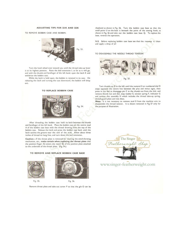
Singer 221 & 222 (Featherweight) Service Addendum
Service manual
6 pages · EnglishRead →
From the ISMACS International. Original publisher and archive notices are retained.
Check the model and edition against your equipment.
PDF verified 2026-10-11.