Sewing machines
Singer 206K25, 206K43, 306, 319, and 401 Service — Service manual
Service manual for Singer 206K25, 206K43, 306, 319, and 401 Service. 174 pages in English. Read the original PDF, download or print a copy without registration.
174 pagesEnglish19.4 MB PDF
Loading your manual…Open PDF directly
Document details
- Brand
- Singer
- Model / document
- Singer 206K25, 206K43, 306, 319, and 401 Service
- Document type
- Service manual
- Language
- English
- Pages
- 174
- File size
- 19.4 MB
- Category
- Sewing machines
- Document date
- Not specified in catalog
Search available document text
Find a term, then jump to its page in the original PDF. Image-only pages may not be searchable; check the PDF for exact wording and diagrams.
Page 1 · Read text
Form 20732
            Printer in ll S A

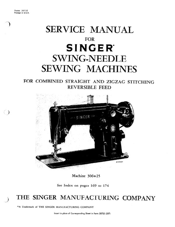
       SERVICE MANUAL
                     FOR
      SINGER
        SWING-NEEDLE
     SEWING MACHINES

      FOR COMBINED STRAIGHT AND ZIGZAG STITCHING
                   REVERSIBLE FEED


                        "SINGER S


                                   Machine 306w25


                               See Index on pages 169 to 174

THE SINGER MANUFACTURING COMPANY

        *A Trademark of THE SINGER MANUFACTURING COMPANY


                                                          Insert in place of Corresponding Sheet in Form 20732 (257)
View original page 1Page 2 · Read text
PROPERTY OF

        THE SINGER MANUFACTURING COMPANY


This is a private and confidential communication to and for the use of only

the employees of The Singer Manufacturing Company and its affiliated com-

panies. Reproduction, sale, distribution, or publication thereof to the public

is forbidden.
View original page 2Page 3 · Read text
TABLE OF CONTENTS


                                                           Pace
 SINGER Automatic Swing-Needle Sewing Machines ........             3 to 79

 SINGER Non-Automatic Swing-Needle Sewing Machines of Class 306 and
     Machine 206K43                                                   81 to 85

 SINGER Non-Automatic Swing-Needle Sewing Machine 206K25        87 to 102

 SINGER Automatic Swing-Needle Sewing Machines of Class 319       ..103 to 123

 SINGER Automatic Swing-Needle Sewing Machines of Class 401           ..125 to 162

  Descriptions of Machines ......                                            ....163 to 168
Index                                                   169 to 174


SINGER AUTOMATIC SWING-NEEDLE
          MACHINES

  The instructions on the following pages, up to and includ
ing page 79, apply to 306 Automatic Swing- Needle Machines.
View original page 3Page 4 · Read text
TiPS ON SETTING UP


   After removing the machine from its packing case,      6. By means of an oil can filled with Varsol,
 set it up in the order noted below.                         flood the sewing hook assembly. Run ma-
                                                   chine for about three to five minutes until  1. Inspect for concealed damage incurred
                                                                      all the tacky oil is washed out. Then ap-    during transit, typical forms of which are
                                                       ply SINGER Oil and run-in the machine    as follows:
                                               again for three to five minutes.
     Bent arm shaft.
     Broken or bent hand wheel.                           7. Oil the sewing machine completely. See pages
                                          74 to 77. Wipe away all surplus oil.    Cracked or bent bed.

    Noisy gears (high pitched whining gear tone as     8. Make sure there is heat expansion clearance
        well as gear growl) caused by severe shock.         .015 to .020 inch between rear arm shaft bush-
    Machine bound tight by severe shock.                  ing and flanged bushing. See page 27.

    Broken or bent under-bed parts.
                                                             9. Inspect condition of needle before making sew-
    Broken or cracked motor end covers, light and                                                            ing test. See page 5. Check hook and needle
      pulley.                                                                      relationship.
    Broken or bent stitch regulator lever.
                                                      10. Sew-in the machine and check the stitching for    Water damage (observe for water marks inside
                                                              correct behavior of bight controls and pendulum        carton).
                                                        motion. See pages 52 to 55.
 2. Turn hand wheel over toward you to make cer-
     tain that sewing mechanism turns freely.          11. Make sure stitch regulator moves freely; that it
                                                  does not creep when sewing or that it sticks or
 3. Wipe off all traces of the tacky anti-rust oil used                                                                   binds.
    to protect the polished and plated surfaces.
    Give particular attention to the needle thread     12. Test wind a bobbin to be sure that bobbin winds
     tension assembly.                                          evenly.

 4. Apply motor and light to machine and check     13. Check bobbin case tension with silk as described
    operating behavior.                          on page 21.

5. Remove bobbin case and wash in Varsol, mak-                                                   14. Polish the head to a satin finish. Do not leave
    ing sure all traces of tacky oil have been                                          an oily or a greasy film on any portion of
   washed out from under the tension spring.            the head or the cabinet.
View original page 4Page 5 · Read text
ORDER OF INSPECTION OF CUSTOMER'S
)                        MACHINES AT THE BENCH

         1. Obtain complete information concerning the    7. Check relationship of needle with sewing hook.
            customer's sewing problem before making any       See pages 9 and 41 to 44.
            adjustments.

                                                               8. Check pendulum motion of needle bar. See
         2. Obtain samples of the customer's material and
                                                   pages 52 to 55.
           thread for final testing.

         3. Check threading of machine.                           9. Inspect hook timing at central position of needle.
                                                See page 43.

         4. Inspect needle for-

                                                            10. Check needle bar height at extreme left needle                  a. Make. All SINGER needles are marked with
                                                                        position. See page 44.              the Company's trademark SIMANCO *

            b. Comparison of size with the thread used.
                                                            11. Check feed mechanism for-
            See page 10.

                                                                            a. Timing of feed movement. See page 29.
                   c. Damage (Needle bent or blunt-needle eye
                rough.)                                             b. Feed dog height. See page 30.

             d. Relation to needle hole in throat plate. Check          c. Position of feed dog in throat plate slots.
                  for straight sewing and for maximum zigzag          See page 32.
                 stitching. See pages 22 and 52.
                                                                     d. Test feed for slight forward motion at "O',

        5. Check condition of needle hole (or slot) in
           presser foot and in throat plate.                  12. Test bight controls, using needle perforation
                                                                            tests. See pages 58 and 59.

         6. Check thread clearance between position finger
         and bobbin case holder. See page 42                                                              13. Check arm shaft connection belt for looseness.


                                  5

                                                              Insert in place of page 5 in Form 20732 (257'
View original page 5Page 6 · Read text
SUGGESTIONS TO THE SERVICEMAN IN THE NOME


   Quite frequently, when a machine is not sewing         c. location in:
 satisfactorily, the required adjustments can be accom-                throat plate
 plished in the home by a SINGER Serviceman.                  presser foot

                                                                             relation to sewing hook point

   Conditions such as faulty operation of the bight
                                                                d. damage from striking hook point
control or worn or damaged parts may have to be

 remedied at the SINGER Shop, but this decision should                                                           4. Check threading of machine, both upper and
 be made only after the machine is thoroughly checked                                                          under threads.
in the exact order outlined below.

                                                             5. Check tensions of both threads. See pages 15
                                                  to 21.  Use a Checklist similar to one shown on page 7
 as a record for the man at the bench.
                                                        6. Inspect wound bobbins for proper winding.
                                            See page 79. Bobbin must turn freely inside
                                                    bobbin case.
ORDER OF INSPECTION IN THE HOME

                                                     7. Inspect thread take-up springsettings.See  1. Inspect recent samples of sewing made by the
                                               pages 19 and 20.     customer on the machine, before checking ma-
     chine itself. Ask customer to indicate on sewing
                                                            8. Check hook and needle relationship. See pages
    samples the particular stitching faults she has                                                   9,41, 43 and 44.
   made reference to.

                                                          9. Check timing of needle bar and sewing hook
 2. Check the combination of needle and thread         during straight stitching. See page 43.
    used by customer. See page 10.
                                                    10. Check position finger in bobbin case base for
                                                         proper thread space. See page 42.
 3. Check needle for-

                                                        11. Check height of feed dog; its position in throat
         a. wear or damage (needle blunt, bent or
                                                                        plate.
         burred).

      o. position in needle clamp. See pages 12 and    12. Check performance of bight control mechanism.
       88..                                   See pages 62 to 67 and 92 to 99.
View original page 6Page 7 · Read text
SAMPLE CHECK LIST
)                      FOR SERVICEMAN IN THE HOME
         ITEMS REQUIRING ATTENTION ARE INDICATED BY CHECK & MARK:

        1. QUALITY OF STRAIGHT STITCHING -CENTRAL           RIGHT.           LEFT

        2. ZIGZAGS IN STRAIGHT SEWING POSITION [ STAGGERS O

         3. FRAYS AND BREAKS SILK THREAD DURING -CHAINING                 #25 STITCH.
         FRAYS AND BREAKS MERC. COTTON THREAD DURING- CHAINING -          #25 STITCH.
       FREE-HAND EMBROIDERY D ZIGZAG SEWING [ STRAIGHT SEWING O

        4. QUALITY OF SATIN STITCH

        5. QUALITY OF ZIGZAG STITCHING_

         6. QUALITY OF TWIN NEEDLE SEWING.

        7. STALLS ON SATIN STITCHING O SEWS IN REVERSE AT "O" D

       8. MACHINE HARD TO START O KNOCKS AT HIGH SPEED D

       9. NEEDLE RUBS THROAT PLATE LEFT SIDE.        RIGHT SIDE

        ) 10. RELATION OF HOOK TO NEEDLE-TOO FAR AWAY [7 STRIKING NEEDLE

      11. HOOK TIMING-SLOW O FAST [J

      12. SKIPS ON STRAIGHT STITCHING O ON ZIGZAG O

     13. MACHINE LOOPS [ GATHERS

      14. HOOK RATTLES O]      FEED NOISY                   TAKE-UP LEVER
                                    IN LOW POSITION O         LOOSELY FITTED •

     15. BIGHT CONTROLS--EASY [7 HARD O TO MOVE
View original page 7Page 8 · Read text
NEEDLES AND THREADS


    For perfect stitching, the selection of the Class,     constant, maintaining an identical relationship be-
  Variety and Size of a needle to be used must be based    tween short-groove side of all 206 × 13 and 306 × 1
  upon the design and capacity of the particular sew-     needles and the hook point. Therefore, any increase
  ing machine as well as the work to be accomplished.     in the diameter of the blade results in a shifting of
                                                      only the centerline of the needle blade away from
                                                       the hook point.

                                      The distance Y, Fig. 2 from the butt-end
  For efficient and attractive sewing results, the    of the shank of the needle to the top of the
  needle blade is designed to be as slender as possible,                                                   needle eye is constant, regardless of needle sizes,


                             FLAT SIDE                      BLADE
                         OF SHANK


                                                   Fig 2. Needle Distances


 while sufficiently strong to avoid breakage at the                                                          within all Classes and Varieties of needles recom-
 needle eye. Therefore, the size of the needle eye, re-                                          mended for a particular sewing machine. This is to
 quired by the thread, determines the ideal size of the                                                      maintain the correct relationship of the height of the
needle blade. The actual size number of the                                                 needle eye to the point of the hook, throughout all
 needle is based upon the diameter of the                                                         possible changes of needles, as listed for the sewing
 needle blade at the eye of the needle. This    machine.
 diameter is constant for all sewing machine
needles of the same size number.                   However, the size of the needle eye increases with
                                                          the size of the needle to accommodate heavier thread.
  The distance X between the short-groove side     Therefore, any increase in the length of a needle
 of the needle blade and the position of the flat-side      for one particular machine is made from the top of
of the needle shank, seated in the needle bar, is                                                    the needle eye toward the point of the needle.


                              8
View original page 8Page 9 · Read text
HOOK AND NEEDLE RELATIONSHIP


                                                     Fig. 3.

                                         Relationship of Hook Point to Needle Eye


    The hook point should pass the needle as close as possible, without striking it. This will insure
hook point entry of thread loop during ornamental zigzag stitching. Adjust by loosening screw M4 and proceed
as instructed on page 41.
View original page 9Page 10 · Read text
CHART SHOWING RELATIONSHIP OF TYPES OF FABRICS,

                     THREAD AND NEEDLE SIZES AND

                      MACHINE STITCHES TO THE INCH


                                                              MACHINE STITCHES
                                                        PERINCH
                              THREAD        NEEDLE       INSIDE       TOP
     TYPES OF FABRIGS           SIZES           SIZES       SEAMS       STITCHING

Filmy material comparable to Net,   Mercerized 00
  Marquisette, Chiffon, Silk and Chif    100 Cotton                                9        15 to 20      15 to 20  fon Velvets, Voiles, Ninon         00 and 000 Silk
                                      Nylon Thread
 Sheer materials comparable to
                                         Mercerized O Lawn, Dimity, Synthetic Sheers,
                               80 to 100 Cotton
 Paper Taffetas, Pure Silks, Gossa-                                12 to 15       15 to 20                                        0 Silk
 mer Silks, Silk or Synthetic Tricots,
                                      Nylon Thread Synthetic Velvets, Satins

 Lightweight materials comparable
   Gingham, Chambray, Pique,    Mercerized 50
 Poplin, Percale, Cretonne, Chintz,   60 to 80 Cotton
 Faille, Bengaline, Wool Flannel,     A Silk          14                          15 to 18
 Wool Jersey, Wool Crepe, Cotton   Nylon or Dacron
 Velvets and Velveteens, Lightweight      Thread
 Suitings

 Medium heavy materials compar-
able to Corduroy, Crash, Gabar- Heavy Duty Merc. 40                                   16       10        12 dine, Rep, Heavy Suitings and Coat-40 to 60 Cotton
ings
Heavy materials comparable to
                              30 to 40 Cotton Sailcloth, Denim, Ticking, Over-                                                                10                                   18      8                              Dacron Thread coatings

  Plastic materials                  Mercerized 50
                                                            10


                            TWIST OF THREAD

   For ordinary stitching, either right or left twist
 thread can be used in the needle and in the bobbin.               HOLD THIS END
                                                                                         ROLL OVER


   To determine twist of thread, hold thread as shown
 at right and turn thread over toward you between
 thumb and forefinger of right hand. If thread is left
 twist, the strands will wind tighter; if right twist, the
 strands will unwind.                                                        Fig. 4. Determining the Twist of Thread


                           10
View original page 10Page 11 · Read text
TO ORDER NEEDLES FOR SWING-NEEDLE MACHINES


        Single needles for these Machines are of Class
                                                        thread will interfere with the successful use of the
                                                  machine.
and Variety14, 16 and20618.x 13 and are made in Sizes 9, 11,
                                                 Whenever a machine breaks thread or skips, try
                                                            the next size larger needle.
       The size of the needle to be used depends upon the
      size of the thread which must pass freely through the      Orders for needles must specify the Quantity re-
     eye of the needle.                                                              quired, the Size number, also the Class and Variety
                                                    numbers, separated by an x.

      Do not use rough or uneven thread or thread which
                                                   The following is an example of an intelligible order:
     passes with difficulty through the needle eye, as such
                                                             "100 No. 18, 206 x 13 Needles.


                     DESCRIPTION OF 306 x 1 TWIN NEEDLES

     Twin-needles of Class and Variety 306 × 1,
                                                                     "100 No. 14, 306 × 1-3 Needles."
    moulded together in one assembly, are made in Sizes
    11 and 14 for a maximum bight of 3mm. Always
     include desired bight when ordering, as shown by
                                              The best stitching results will be obtained with
    the following example:
)                                                   needles sold by Singer Sewing Machine Company.

                    15 x 1 NEEDLES FOR MACHINES OF CLASS 401


     These machines use needles of Class and Variety
                                                           15 x 1, available in sizes 9, 11, 14, 16 and 18.


                     TO PREVENT BREAKING OF NEEDLES

     The most common cause of needle breakage is the
                                                   unless the correct relative position between the
    pulling of the material by the operator, while the ma-
                                                        needle, throat plate and presser foot is maintained,
   chine is sewing.. This practice is entirely unnecessary,                                                  as instructed on page 52.
   as the machine (when properly adjusted) will feed the
    material correctly without assistance                   The needle or the hook point may break unless the
                                                   machine is correctly timed, as instructed on pages 41
     Attempting to perform zigzag stitching, while the   and 43.
  machine is fitted with straight stitching throat plate
  or presser foot, will also cause breaking of needles.   NOTE: Do not exceed number three on bight
                                                control when sewing with twin
    The needle may break unless it is correctly located
                                                         needles, otherwise bending or break-
   yin the needle clamp, as instructed on page 12, or                                              age will occur.


                                        11

                                                        Insert in place of page 11 in Form 20732 (257)
View original page 11Page 12 · Read text
LOGATION OF NEEDLE IN NEEDLE CLAMP


     If the needle is incorrectly placed in the needle     Fig. 6, facing the rear of machine, away from the
clamp and is incorrectly threaded, the machine will     operator, then securely tighten needle clamp thumb
nor saw                                         screw.


       MOVE TO
                       NEEDLE CLAMP
           HIGHEST
                    THUMB SCREW
          POINT


                                                                                   FLAT SIDE
                                                                TO REAR
                            INSERT NEEDLE
                      UP AS FAR AS
                             POSSIBLE
      LONG GROOVE
         TO FRONT ->
                                                                                 SHORT
                                                                              GROOVE


                 Fig. 5. Setting the Needle                               Fig. 6. Flat Side of Needle (Enlarged)


  Make sure that needle is not blunt or bent.         You will note from Fig. 6 thot the side of the
                                                   needle with the flat on the shank has a short groove

                                                            at the eye, while the opposite side, shown in Fig. 5,
                                             has a long groove. On all machines the needle is
  Loosen needle clamp thumb screw and insert needle     threaded from the long groove side toward the short
in the needle clamp slot, all the way up against the     groove; thus the needle on this machine is threaded
stop, with the flat side of the shank of the needle, see    from front to rear.
View original page 12Page 14 · Read text
FORMATION OF THE LOCK STITCH (Continued)


                -THREAD TAKE-UP
                                                   THREAD TAKE-UP
                      LEVER                                                                    LEVER


                    WAN SIT


                    TENSION                                                         TENSION
                     DISCS                                                      DISCS


              NEEDLE                                                             • NEEDLE

             PRESSER FOOT                       PRESSER FOOT


    BOBBIN     HOOK POINT                                       HOOK-     BOBBIN CASE
    CASE
                                                 POINT
                 ROTATING HOOK                                                                                                          - ROTATING HOOK


     Fig. 9. Bobbin Thread Enclosed by Needle Thread                              Fig. 10. Stitch Completed


   Fig. 9 shows the third stage. The loop of the        Fig. 10 shows the final stage of locking the stitch.
needle thread has been cast off the hook and the    As the take-up lever rises to its highest position, the
take-up lever is rising quickly to take up all the slack   feed dog is completing its forward motion, thus lock-
thread.                                                    ing the two threads into a lock stitch.
View original page 14Page 15 · Read text
THE PERFECT LOCK STITCH


                     Fig. 11. Cross Section View
                        of Perfect lock Stitch                                      Fig. 13. Cross Section View of Lock Stitch
                                                                                 with Loose Needle Thread Tension


   When the tensions of both the needle thread and
                                                    Irregular stitching, such as is shown in
  the bobbin thread are correctly adjusted, the stitches
                                                        Fig. 14, is usually caused by a combination of
   will be locked in the center of the thickness of the
                                          two or more of the following conditions:
   material, as shown in Fig. 11.

   When the tension of the needle thread is set too
                                                           a. Too loose or too tight needle thread tension.
  tight in relation to the bobbin thread, excess bob-
                                                              b. Too loose or too tight bobbin thread tension.


         Fig. 12. Cross Section View of Lock Stitch with
                 Tight Needle Thread Tension                                     Fig. 14. Cross Section View of an
                                                                                             Irregular Lock Stitch


 bin thread is drawn to the top of the material, causing
                                                                              c. Damaged or improperly set tension spring on
 a loose stitch, as shown in Fig. 12.                                                             bobbin case.
  When the tension of the needle thread is set too     d. Worn or damaged position finger.
loose in relation to the bobbin thread, excess          Bent needle or damaged needle eye.
 needle thread is drawn to the bottom of the material                                                         Improper feeding of material.
 and the bobbin thread may lie straight along the un-
                                                               g. Use of wrong needle and thread combination.
derside of the material, as shown in Fig. 13.
                                                         h. Incorrect feed time.


                           15
View original page 15Page 16 · Read text
TENSION CONDITIONS


  When checking and adjusting machine for tension    proper tension of machine is to start with longest
 conditions in relation to perfect sewing, use a Size 14      stitch and make sure that no looping appears in the
 needle and "A" silk thread. Silk thread should be used    stitching. Then shorten stitch to approximately #25
 to establish proper "O' setting of needle thread ten.    and note whether or not tension is satisfactory. If
sion and bobbin thread tension should be adjusted     noticeable variations occur, make sure all traces of
 with silk as described on page 21. After completing     the tacky anti-rust oil are removed from the polished
sewing tests with silk, repeat these tests with #50    surfaces of the sewing hook and tension parts. See
mercerized cotton thread. Silk thread will show up     instructions on page 4. Failure to wash the hook
any tendency for the machine to skip, fray or break     with Varsol and to oil it after cleaning, may result in
thread before such conditions would be noted with    many forms of looping trouble.
mercerized thread.

   Test the machine at the following settings:           SATIN STITCHING

     1. Straight sewing at left-, central and right-     When satin stitching, feed and tension adjustments
       hand position of needle and at both longest    must be very carefully made to insure a uniform
        and shortest stitch setting.                        quality of satin stitch. Cording of fabric can be ex-

                                                     pected if excessive needle thread tension is employed     2. Maximum zigzag stitching at extreme left-
                                                     or if "O" dial tension setting is too high.
      and right-hand position of needle and at
        both longest and shortest stitch settings.

                                       OPEN ZIGZAG STITCHING
STRAIGHT STITCHING
                                         On open zigzag stitching it is not always possible to
  The amount of needle thread tension required to     lock the stitch in the corners without cording the fab.
make a satisfactory straight stitch will vary with each      ric unless 1 or 2 thicknesses of some crisp underlay,
machine. A closely fitted hook may require between                                                such as organdy, are used. When underlay is used,
#5 and #7 on dial tension. A loosely fitted hook may     additional needle thread tension may be required to
require between #4 and #6. The safest test to insure    lock the stitch in the corners.


                                     16
View original page 16Page 17 · Read text
SEWING DIFFICULTIES                                 CAUSES               REMEDIES

                                            Needle too small for size   Use correct needle. See page
                                                    of thread.              10.

                                    Too little needle thread    Increase upper tension. Check
                                                tension. Faulty take-up     stroke of spring--replace if neces.
                                                    spring action.               sary. See pages 19 and 20.

     Irregular setting of stitches with large beads                            Free hook of any threads, gum
    showing on the underside of the fabric.      Clogged or sticky sewing     or other foreign matter. If neces-
                                          hook.                                                                      sary replace hook and bobbin
                                                                      case holder.

                                                                       Provide .020 inch thread space
                                                                   between bobbin case holder and
                                                           Insufficient thread space.
                                                                          position finger. See page 42.
                                                                              Inspect finger for roughness.

                                       Needle thread tension   Reduce tension.
    Fabric drawing on open zigzag stitch of     too tight.
   medium stitch length.
                                      Pressure on take - Up   Reduce pressure on take-up
                                                                              spring. See page 20.
)                                                spring is too great.                                                         Reduce tension so that material
                                                                                             is not drawn yet stitch lies flat.    Fabric drawing on all short zigzag stitching    Needle thread tension
                                                                     Underside stitching will not lock   from medium to maximum bight.              too tight.
                                                                                         in corners but in between needle

                                                                                       perforations.

                                                            Tension must be lighter for   Material drawing when sewing with Silk,
                                       Upper tension too tight.    synthetic threads than for cotton.   Nylon or Dacron Threads.
                                                               Reduce tension.

                                                     Use a solid foot in place of a
                                                  Material may be flagging
   Machine skipping at extreme left or right                                                                hinged foot. Replace needle.
                                                   with needle. Needle may
  needle position when sewing with Silk or                                                          Check height of needle bar in
                                   be bent or setting too   Nylon threads.                                                                                   relation to hook. See pages 44
                                            high.
                                                  and 45.


    All adjustments on needle thread tension, see page    bobbin thread tension is correctly set at the factory
   18, should be made on the assumption that the    and should not be unnecessarily disturbed.
View original page 17Page 18 · Read text
TO REGULATE THREAD TENSIONS


NEEDLE THREAD TENSION

   This machine is equipped with a one-cycle dial ten-
sion which, when set correctly, offers a barely per-
ceptible tension at "O" to a maximum at the end of
one complete rurn or thumb nur


  At "O" there should be a barely perceptible amount

of tension, as otherwise, difficulty may be experienced
when sewing with twin needles, satin stitching and
other forms of closed ornamental stitching.                                   Fig. 15. "O" Setting


   Pull thread through tension discs to test amount     of no tension. Then advance one hole to right to give
of tension on thread at "O" position. At this point    minimum tension at zero position.
there should be a slight pull on the thread to indicate
                                      TO OBTAIN INGREASED TENSION RANGE
there is a minimum tension which gradually increases
with the turning of thumb nut A to the right, providing     On some occasions a slight increase in maximum
  a full range of tensions with one revolution of the    range of needle thread tension may be required for
thumb nut. If the pull is too strong for a minimum      special work.
tension, press in dial C to disengage pin B on nut      The additional tension may be obtained by using
from dial, and reset pin in next hole to left of previous     tension indicator No. 125415 and tension spring No.
setting. Repeat this adjustment until a point is reached    45869 if the machine is not equipped with these parts.


             TO REMOVE AND DISASSEMBLE NEEDLE THREAD TENSION


  Turn thumb nut A over to the left (counter-clock-    remove it. Then remove tension parts from stud as
wise) until it stops. To separate pin B in thumb nut A    shown in Fig. 16.
from dial C, press in dial, unscrew thumb nut and
View original page 18Page 19 · Read text
TO REASSEMBLE AND REPLACE NEEDLE THREAD TENSION

          Place tension parts on the stud as illustrated:         3. Tension spring must be mounted so the half coil
                                                                          at front is in the lower position.        1. Make sure tension discs are free of oil, grit or)
          grease.

        2. Indicator must show plus and minus signs at top      4. Finger of slotted washer must point upward to
             for operator's convenience.                                                                      act as a stop for dial.


        060


                                                                                                    Е24740


                                                    Fig. 16. Needle Thread Tension Assembly
)
                  TO ADJUST THE THREAD TAKE-UP SPRING

   STROKE OF SPRING                                        TO SET TAKE•UP SPRING STROKE

     The take-up spring J, Fig. 17 should be at rest      Loosen set screw L, Fig. 17.
     against its stop as the point of the needle enters the     Rotate tension stud Z clockwise with a screwdriver
    fabric.                                                         (turning whole tension assembly) to complete its action
                                                 over.
                                                    Rotate tension stud Z counter-clockwise with a
    When adjusting take-up spring, the stroke                                                             screwdriver (turning whole tension assembly) to com-
   must be adjusted first, then followed by the     plete its action earlier.
    pressure of the spring.                                                         Securely tighten set screw L.


                                         G8


                           Fig. 17. Setting                                                    Fig. 18. Removing
                      Stroke of spring                                        Tension Assembly

                                    19
View original page 19Page 20 · Read text
PRESSURE OF SPRING                                      Insert assembly into machine with plus and minus

                                                         signs of indicator in uppermost position and hold ten-

                                                            sion assembly in place.
   Tension on thread take-up spring should be just
  sufficient to take up slack of needle thread until needle     Move loop of spring to the left so that it may come
 point reaches the fabric.                                     to rest against its stop.


          1.8

                                   E25055                E25056

                     Fig. 19. Showing                                                                                      Fig. 20. Spring
                     Spring                                                  Left of Center Line


   Excessive pressure will cause fabric to cord (draw)       Securely tighten screw G8, Fig. 18.
 during satin stitching or wide bight zigzag stitching.
                                                             Test pressure of spring to determine if a finer adjust-
                                            ment is needed.
    Insufficient pressure will cause looping or thread
breakage.                                  NOTE: If more pressure is required, move small tail
                                                                   of spring L8 into the next stud slot to the
                                                                           right of previous setting.

                                                                                                     If less pressure is required, move small tail of springTO ESTABLISH MINIMUM PRESSURE OF SPRING
                                                L8 into the next stud slot to the left of previous setting.

   Turn screw G8, Fig. 18 counter-clockwise and   NOTE: A very fine adjustment for pressure of the
remove tension assembly.                                        spring can be had by loosening screw G8,
                                                                 Fig. 18 and turning complete assembly
                                                                clockwise to increase pressure and counter-
   slide spring on tension assembly so that tail of
                                                                 clockwise to decrease pressure.
 spring L8, Fig. 19 is in one of the stud slots and top
 of spring J, is just left of center line on indicator in              Retighten screw G8 and test spring pressure
 the area between dotted lines, illustrated in Fig. 20.            by sewing.


                                     20
View original page 20Page 21 · Read text
TO REGULATE BOBBIN THREAD TENSION

    BOBBIN THREAD TENSION

       The tension on bobbin thread is regulated by the)
       larger screw nearest the center of tension spring, as
     shown in Fig. 21.

      When adjusting bobbin tension, a slight turn of the
      screw is all that is needed to make a fine adiustment

     because the full range of tension from zero to a maxi-

    mum is made within 1-1/4 turns of tension regulating


                 MORE
                    TENSION


                                                                  E23575

                   LESS                                              Fig. 22.
                    TENSION
                                                   SUGGESTED METHOD                 E74.739
                                            FOR SETTING BOBBIN THREAD TENSION
                          Fig. 21. Bobbin
                        Thread Tension                   Wind bobbin with a 50 yard spool of sixe "A"
                                                           silk thread.

                                                    Thread bobbin case and adjust tension so that
       To increase tension, turn this screw gradually over
                                                        weight of bobbin case with a bobbin of 50 yards of
      to the right.
                                                                         "A" silk will cause case to slide slowly, when held sus-

                                                 pended by the thread. See Fig. 23. For correct ten-
       To decrease tension, turn this screw gradually over                                                                 sion, its downward movement should be very slow.
     to the left.


    TO REGULATE BOBBIN THREAD TENSION WITHOUT

    REMOVING BOBBIN CASE


      The thread tension screw is conveniently adjusted
     while bobbin case remains in machine.


       To adjust, raise take-up lever almost to its highest
      point, tilt machine back on its hinges and turn the
     large screw on the bobbin case as shown in Fig. 22.


      Turn screw over away from operator to loosen ten.

 @ sion or over toward operator to tighten tension.                        Fig. 23. Checking Bobbin Thread
                                 21                    Tansion
View original page 21Related documents and language editions

SingerPDF
Singer 101-1
Parts list
42 pages · EnglishRead →
SingerPDF
Singer 101-1, 101-2, 101-3, 101-10, & 101-11 Adjusters
Service manual
48 pages · EnglishRead →
SingerPDF
Singer 101-2, 101-3, 101-10 & 101-11
Parts list
136 pages · EnglishRead →
SingerPDF
Singer 101-3 & 101-11 Adjuster's
Service manual
20 pages · EnglishRead →
SingerPDF
Singer 115-1 & 115-2 Parts List
Parts list
38 pages · EnglishRead →
SingerPDF
Singer 128-8 Parts List
Parts list
20 pages · EnglishRead →

SingerPDF
Singer 15-86 & 15-87 Parts List
Parts list
61 pages · EnglishRead →
SingerPDF
Singer 15-88, 15-89, & 15-90 Parts List
Parts list
63 pages · EnglishRead →
SingerPDF
Singer 201-1, 201-2, 201-3, 201-4, & 1200-1 Adjuster's
Service manual
72 pages · EnglishRead →

SingerPDF
Singer 206K25 Service
Service manual
28 pages · EnglishRead →
SingerPDF
Singer 221 & 222 (Featherweight) Service Addendum
Service manual
6 pages · EnglishRead →
SingerPDF
Singer 221 (Featherweight) Adjusters
Service manual
20 pages · EnglishRead →
From the ISMACS International. Original publisher and archive notices are retained.
Check the model and edition against your equipment.
PDF verified 2026-10-11.