Sewing machines
Singer 221 (Featherweight) Service — Service manual
Service manual for Singer 221 (Featherweight) Service. 31 pages in English. Read the original PDF, download or print a copy without registration.
31 pagesEnglish7.5 MB PDF
Loading your manual…Open PDF directly
Document details
- Brand
- Singer
- Model / document
- Singer 221 (Featherweight) Service
- Document type
- Service manual
- Language
- English
- Pages
- 31
- File size
- 7.5 MB
- Category
- Sewing machines
- Document date
- Not specified in catalog
Search available document text
Find a term, then jump to its page in the original PDF. Image-only pages may not be searchable; check the PDF for exact wording and diagrams.
Page 1 · Read text
Supplement to
 Form 21325
Machine 221
(566)


         SERVICE MANUAL
     SINGER

             MACHINE 221


                                - THE SINGER COMPANY

 *A Trademark of THE SINGER COMPANY                                                            Printed in U. S. A

            www.Singer-Featherweight.com
View original page 1Page 4 · Read text
DESCRIPTION

     Lightweight portable lockstitch machine with        The motor is mounted on machine bed. Wiring to
  reversible drop feed and electric drive.                  motor and light is concealed in machine arm and
                                                      bed. The machine is equipped with a foot controller.
    Graduated stitch length indicator.                      (Note: Machine 221K4 is also equipped with R. F.
                                                       Suppressors and grounded wiring.)
    Numerically graduated thread tension device.
                                                              Light and light shade attached to front of ma-
    Rotary hook on horizontal axis, makes two rev-       chine arm with control switch located on bed. (Ma-
 olutions per stitch.                                  chine 221K4 has light switch built into the light
                                                                socket.)
    Machine 221K7 is equipped with belt linkage be-
 tween arm and hook shafts. Other varietiesare         Machine base 10-7/64 inches long, 7-1/4 inches
 equipped with an upright arm shaft and gears                wide. Space at right of needle, 5 inches.

    Hinged bed extension.                                 Presser bar light: 5/16 inch. Feed dog height:
                                                                   .040 inch above throat plate.
    Manually controlled bobbin winder attached to
belt guard.                                                    Maximum stitch length: 6 stitches per inch.

    Needle, Cat. 2020 (15×1), threaded from right            Speed range: 900 to 1400 г. p. m.
to left.


                             PRINCIPAL PARTS AND FEATURES

       PRESSURE REGULATOR  THREAD TENSION LIGHT SPOOL PIN  ARM TOP COVER


  TAKE-UP LEVER                                                                                                                        - HAND WHEEL

 FACE PLATE.                                                                 BOBBIN WINDER


                                                                          STITCH LENGTH
  PRESSER FOOT LEVER                    SINGER                            REGULATOR


  THREAD CUTTER                                                  MOTOR BELT

                                                                                LIGHT SWITCH


  PRESSER FOOT


  THROAT PLATE                                                                                                                    - BOBBIN-WINDING
                                                                    THREAD GUIDE


        BED EXTENSION                                                       221-1- SERIES 3
                                                      221K4. CAK7
                                  MOTOR
                                                      221K5- CAJ6-8
                       FEED DOG                221K7: CAK8-8    ELECTRICAL CONTROLLER
View original page 4Page 5 · Read text
PREPARATION FOR INSPECTION


    Before inspection to find causes of faulty opera-        CAUTION: KEEP VARSOL AWAY FROM ALL
  tion, the machine should be thoroughly cleaned    RUBBER PARTS.
 and lubricated.
                                                          Note: Under extreme conditions (if grease and
    Remove face plate and throat plate. Open arm         dirt is hard and tacky remove motor, light and
 top cover and remove bottom cover.                           wiring, as instructed on page 25, and soak machine
                                                                         in a tank of varsol until solids have become softened.
   Remove lint and other foreign matter that may
have accumulated around the sewing area and clear         CAUTION: Before dipping Machine 221K7 in
all exposed moving parts with a broom type nylon         varsol, it will be necessary to remove the Arm Shaft
 brush dipped in varsol.                                  Connection Belt, as instructed on page 24.


                                      LUBRICATION

                         Use SINGER* OIL and SINGER* LUBRICANT


    With the face plate removed and arm top cover
 removed or turned aside, apply a small amount of oil
 or lubricant to each of the points indicated in Fig
 3, 4 and 5. Close arm top cover and replace face
 plate.            otherw


                                                                        Fig. 4. LubricationI of Hook


                                                        OIL         OIL     LUBRICANT
                                                                                   (Gear Driver
                                                                                Machine Only


                                                                  • OIL


                                         "OIL

      OIL


          Fig. 3. Lubrication - Inside Face Plate                       Fig. 5. Lubrication - Rear and Top
View original page 5Page 6 · Read text
Turn machine on its side, remove bottom cover       dicated in Fig. 6. Replace bottom cover.
 and apply oil or lubricant to each of the points in-

                      OIL    OIL            LUBRICANT              OlI
       OIL                                                   (Gear-Driver
                                                         Machine Only)


    BITTED


  OIL


  OIL


                 OIL                                          OIL


                                             MOTOR
                                                     LUBRICANT
TO LUBRICATE THE MOTORoer-

  Never use of orC ordinary gear grease to lubricate
 motor. Entrance of ojl into motor may cause failure
 of electrical components. Use MOTOR LUBRICANT
 sold by The Singer Company.

   The fwo motor grease tubes, Fig. 7, should be
refilled every 6 to 12 months, depending on machine
 usage.


                                                                                Fig. 7. Lubrication - Motor
View original page 6Page 7 · Read text
TO SET THE PRESSER FOOT HEIGHT


  GUIDE BRACKET
  SET SCREW

                                5/16 INCH

                                             SHOULD BE
                                                  ALIGNED


           Fig. 8. Setting Presser Foot Height                          Floud, Aligning Presser Foot


CHECK:                                    SETTING:

     When presser foot is raised to highest point, dis-         Loosen, guide bracket set screw shown in Fig. 8
 tance between bottom of presser foot and top surface      and raise or lower presser bar as required to obtain
 of throat plate should be 5/16 inch, as shown in Fig.       correct height.
8. (Note: The needle clamp, when at its lowest point;
  should not strike the raised presser foot.)                    Align presser foot with throat plate slots and                    0
                                                       needle as shown in Fig. 9.
    Presser foot should be in alignment with throat
 plate slots and feed dog, as shown in Fig. 9. Inset,          Securely tighten guide bracket set screw.
  Fig. 9, shows correct alignment of presser foot with
 needle


                        TO SET THE FEED DOG HEIGHT

PREPARATION:Singe

 1. Remove bottom cover.

 2. Set stitch length regulator for 12 to 15 stitches

    per inch.

     3. Turn hand wheel toward operator until feed dog

   is in its highest position.


                                                                 Fig. 10. Preparation - Feed Dog Height
View original page 7Page 8 · Read text
CHECK:                                        STRAIGHT EDGE           THROAT PLATE


     With feed dog at highest point, approximately the
 full depth of rear teeth should project above top
  surface of throat plat

SETTING:                               DANAAAAAAAAN

  Loosen hinge nut on FEED LIFTING ROCK
                                               FULL DEPTH OF REAR TOOTH
SHAFT, Fig. 12, and turn eccentric hinge screw
  until high point of eccentric is toward rotary hook                                FEED DOG
  shaft. Then turn eccentric hinge screw as required to
 correct height.
                                                                         Fig. 11. Feed Dog at Correct Height
    Maintain this setting while tightening hinge nut.


                            TO POSITION FEED DOG
                                    IN THROAT PLATE SLOTS


 LENGTHWISE SETTING

 PREPARATION:                                 SETTING:

    Set feed dog height as previously instructed.           Logsen hinge nut on FEED ROCK SHAFT, Fig.
                                                  and turn eccentric hinge screw until high point
CHECK:                                                   of eccentric is away from rotary hook shaft. Then
                                                          furn eccentric screw as required to bring teed doc
    Feed dog should move as close as possible to         in correct position.
front of throat plate slots without striking throaf
plate.                                                     Maintain this setting while tightening hinge nut.


  FEED ROCK SHAFT


                                                                           ECCENTRIC HINGE
                                                                     SCREW


  ROTARY HOOK SHA              NUT


  FEED LIFTING                 NUT
  ROCK SHAFT


                                                                                                                                                - ECCENTRIC HINGE
                                                                     SCREV


                 Fig. 12. Setting Height of Feed Dog and Positioning Lengthwise in Throat Plate Slots
View original page 8Page 9 · Read text
TO POSITION FEED DOG (Cont'd)


        CENTER                 FEED ROCK SHAFT                       CENTER
          SET SCREW                                                              SET SCREW


           CENTER                                                        CENTER
            SET SCREW                                                              SET SCREW


                                      FEED LIFTING
                                        ROCK SHAFT


                                Fig. 13. Positioning Feed Dog Sidewise in Throat Plate


                                      SIDEWISE SETTING:


 PREPARATION:                                         centers in place. To move feed dog toward the left,
                                                          gently tap the right hand center of the feed rock
   Set feed dog heighy as previously instructed.         shaft and feed lifting rock shaft to the left until feed   noe                                                        dog is correctly positioned. Then tighten the four
CHECK:                                                  set screws. To move feed dog toward the right, gently
                                                            tap the left hand centers to the right until teed doc

    Feed dog should be centrally located between         is correctly positioned.

the sides of the feed slots of the throat plate
                                                      NOTE: Check for end play or binding in feed rock
SETTING:                                                  shaft and feed lifting rock shaft. To adjust, loosen
                                                        center set screw at right end of machine and move
   Loosen the four center set screws, Fig. 13, hold-        center as required.

 ing the feed rock shaft and feed lifting rock shaft
View original page 9Page 10 · Read text
TO SET NEEDLE BAR HEIGHT


 USING TIMING MARK

CHECK:                                                               BUSHING
                                                                           SET SCREW
     Turn hand wheel over toward operator until needle
 bar is at its lowest point. At this position, upper
  timing mark, Fig. 14, should be just visible at lower
 edge of needle bar bushing.
                                          NEEDLE
 SETTING:                                   BAR BUSHING

   Loosen clamp screw, Fig. 14, and raise or lower
 needle bar as reauired. Make certain needle bar is                                  UPPER
  correctly turned with long groove in needle facing                                            TIMING
  toward right of machine. Then tighten clamp screw.                                   MARK


 WITHOUT USING TIMING MARK

        If there is any belief that the needle bar bushing
 has been disturbed, it will be impossible to set the
  needle bar by use of the timing marks.
                                              CLAMP          twosSCREW
 CHECK:


    Remove bobbin case and bobbin. With needle X
  threaded, hold thread end and turn hand wheel over                 Fig. 14. Setting Needle Bar Height
  toward operator until needle reaches its lowest point
 and rises approximately 1/10 inch. At this point the
 needle thread loop should be fully formed, Fig. 15,
  and ready for entrance of hook point directly above                               APPROX. 1/10*
  needle eye.                                                   UPWARD
                                                                 STROKE
 SETTING:

   Loosen clamp screw, Fig. 14k and raise or lower
  needle bar as required. Make certain long groove of
  needle is facing toward right of machine and tighten
  clamp screw. Then set the needle bar bushing.

                                          THREAD                                                        • HOOK       TO SET NEEDLE BAR BUSHING
                                             LOOP                              POINT
 CHECK:

     With needle bar set at correct height, turn hand
  wheel over toward operator until needle bar is at its
 lowest point. In this position the upper timing mark
 on the needle bar should be at bottom edge of the
 bushing.

SETTING:                                                                   NEEDLE
                                                                       EYE
     Loosen needle bar bushing set screw, Fig. 14,
  and raise or lower bushing as required. Then tighten
  SET screw.                                                                 Fig. 15. Needle Thread Loop Formed
View original page 10Page 11 · Read text
TO POSITION HOOK TO OR FROM NEEDLE


                                    CHECK:


                                                         Remove throat plate and turn hand wheel over

                                                         toward operator until lower timing mark on needle
                      ноок                 bar is at lower edge of needle bar bushing on its
                                POINT
                                                            upward stroke. With needle bar in this position, the
                                                   distance between the side of needle and point of
                      NEEDLE            hook, as shown in insert in Fig. 16, should be .005"
                                                    This is approximately the thickness of a piece of
                                                              ordinary note paper.
                    .005'
                                                 SETTING:
                             COUNTER-
  ноОК                     BALANCE
  SET
                                                 Loosen counterbalance set screw, Fig. 16, and  SCREW
                                           move counterbalance away from bushing. Loosen one
                                                 hook set screw. Turn balance wheel toward operator
                                                              to position needle bar as instructed above. Loosen
                                                     the other hook set screw and bushing set screw.
                                                Using a 1/4" brass drift pin, gently tap bushing to
                                                                     • SET                  left or right as required. Press hook assembly against
              BUSHING
                               SCREW         bushing and tighten hook and bushing set screws. Re-               SET SCREW
                                                        check setting and replace counterbalance with hub

                                                             against bushing.
   Fig. 16. Distance Between Needle and Hook


                            TO TIMÉ THE HOOK


                                        PREPARATION:

                                                     Set needle bar height and position of hook to or
                                                    from needle as previous y instructed

                           LOWER     CHECK:
                                    TIMING
                            MARK
                                                            With needle threaded, turn hand wheel over toward
                                                    operator until needle bar reaches lowest point and
                                                            rises to position where lower timing mark on needle
                                                         bar, Fig. 17, is just visible at lower edge of needle
                                                   bar bushing. With needle bar in this position, the
                                                        point of the hook should be approximately 1/16"
HOOK POINT                                      above the needle eye and entering the needle thread
ENTERING                     UPWARD      oop
THREAD LOOP                   STROKE

                                          SETTING:

                                              Remove bottom cover. Loosen rotating hook shaft
                                                           pulley set screws, Fig. 18, or hook shaft bevel gear
                                               • NEEDLE EYE
                                                            set screws in gear driven machines. Turn shaft man-                                 1/16 INCH BE LOW
                     HOOK POINT             vally until point of hook is in its correct position
                                                            to the needle eye and needle thread loop, as shown
              Fig. 17. Timing Hook                        in Fig. 17. While holding hook in this position, tighten
View original page 11Page 12 · Read text
TO TIME THE HOOK (Cont'd)


 set screws in pulley or bevel gear.

 CAUTION: In gear driven machines, do not disturb
 mesh of bevel gears.
                                            ROTATING
                                          HOOK SHAFT


                                                                                                                                                                         - SET
                                                                     SCREWS


        NEEDLE THREAD TENSION


 TAKE•UP SPRING STROKE                                                                           Fig. 18. Timing Hook

CHECK:

   The take-up spring, Fig. 19, should complete its                                                          SET SCREW
 action and be at rest against take-up spring stop                                  SLACK
 point of needle enters material                                             THREAD
                                                    LATER             REGULATOR
                                                        ACTION
 SETTING:

                                                                            EARLIER
    To adjust the take-up spring stroke, loosen set        TAKE-UP                       ACTION
 screw, Fig. 19. Move slack thread regulator to the      SPRING
 right to complete take-up spring action earlier
(shorter stroke) or to the left to complete take-up

spring action later (longer stroke). Then securely D tighten set screw.
                                                TAKE-UP
                                                 SPRING
                                                 STOP

 TAKE-UP SPRING TENSION                                          Fig. 19. Setting Take-up Spring Stroke

CHECK:


   Tension on the take-up spring should be just

 sufficient to take up the slack of needle thread until

  point of needle enters material.
                                                                   END OF
 SETTING:                                                                      TAKE-UF
                                                                                  SPRING
   Turn tension dial fo zero, remove face plate and     SET
 loosen stud set screw, Fig. 20. Remove entire ten-      SCREW
  tion assembly from machine. Slide end of take-up
 spring, Fig. 20, out from groove in tension stud.
 Turn end of spring toward right (CLOCKWISE) to in-
                                            DECREASE crease tension or toward left (COUNTERCLOCKWISE)
 to decrease tension and place it in nearest groove.
Replace tension assembly, drawing take-up spring
                                                              INCREASE
up so it rests on take-up spring stop, Fig. 19, and securely tighten set screw.


                                                                          Fig. 20. Setting Take-up Spring Tension
View original page 12Page 13 · Read text
TO ADJUST NEEDLE THREAD TENSION


                                     CHECK:

                                                    With machine threaded, lower presser bar to en-
                    INCREASE                 gage tension and turn tension regulator dial to zerc
                                                            (0) position, Fig. 21. Hold thread on both sides of
                                                  tension regulator and pull back and forth through
                    DECREASE                                                       tension discs. The tension on the thread should be
                                                                just slightly perceptible, which gradually increases
                                                     with the turning of the regulator dial to the right.
                              THUMB
                       PIN   NUT
                                         SETTING:

                                                                                                     If the pull on the thread is too strong for minimum
                                                          tension, press in numbered dial to disengage pin in
                                        thumb nut, Fig. 21, from dial. Reset pin in next
       DIAL                                       hole to the left of previous setting. Repeat process
                                                                until there is ho tension on thread. Then advance
                                                         pin one hole to the right to produce minimum tensi

                                                                 at zero (0) position.

    Fig. 21. Adjusting Needle Thread Tension

                                         TO ADJUST BOBBIN THREAD TENSION


                    INCREASE TENSION
                                     CHECK:


DECREASE TENSION                                   Remove threaded bobbin case and bobbin from
                                                         machine. Hold end of bobbin thread allowing the bob-

                                                        bin case and bobbin to hang free. When tension is
                                                          correctly adjusted, the bobbin case will descend
                                                    slowly each time the thread is given a slight "jerk"
                                                   upward. When using a tensiometer, a bobbin thread      Feattension of approximately 50 grams is sufficient for
                                                    No. 50-3 mercerized cotton
    Fig. 22. Adjusting Bobbin Thread, Tension

                                         SETTING:

                                                          Gradually turn tension regulating screw for either
 ADJUSTING                  PULLEY       increased or decreased tension, as shown in rig. 22
 SCREW


                                            TO ADJUST BOBBIN WINDER PRESSURE


                                     CHECK:


             BELT                                       The pressure of the bobbin winder pulleyagainst
                                                           the belt should be just enough to operate the bobbin
                                                      winder without slippage.

                                          SETTING:

                                                        Tighten adjusting screw, Fig. 23, sufficiently to
          Fig. 23. Adjusting Bobbin Winder               increase pressure of pulley against belt.


                                         12
View original page 13Page 14 · Read text
TO ELIMINATE END PLAY OR BINDING
                          OF HORIZONTAL ARM SHAFT


                                                                  HAND WHEEL
                                                                             BUSHING


    Should the horizontal arm shaft require adjustment
for end play or binding, remove hand wheel as in-
 structed on page 23 to expose hand wheel bushing.
 Loosen set screws, Fig. 24, and move hand wheel
 bushing slightly away from arm shaft bushing. Insert
    a .003 feeler gauge between the two bushings, move
 hand wheel bushing back against the feeler gauge                                                             SET
 and tighten set screw. Replace hand wheel.                                            SCREW
                                                ARM SHAFT
                                                   BUSHINg

                                                                      Fig. 24. Adjusting Arm Shaft End Play


                       TO ELIMINATE END PLAY OR BINDING
                          OF UPRIGHT ARM SHAFT
                               (GEAR DRIVEN MODELS)


                                                             SET
                                               UPPER HORIZONTAL     SCREWS
                                             BEVEL GEAR.
       Feat                      SET
                                                                               SCREWS


    Open top cover and remove bottom cover. Loosen
 set screws, Fig. 25, in lower vertical bevel gear.
 Press downward upon upright arm shaft. Set lower
  vertical bevel gear firmly against lower bushing in                                                                            - UPRIGHT
  casting and securely fighten gear set screw.                                   ARM
                                                                            SHAFT

    Check mesh of upper and lower vertical and hor-
                                          LOWER
  izontal bevel gears to ascertain that they are fully                                                    BUSHING
 meshed. To adjust, loosen horizontal bevel gear set                                                                                           , SET
 screws, Fig. 25, and slide gear to position where it                                      SCREWS
 is correctly meshed with vertical gear. Then tighten
 set screws and replace covers.

   CAUTION: Bevel gears must always be kept in       LOWER
 mesh at all times                                    VERTICAL
                                           GEAR              LOWER HORIZON TAL
                                                                  BEVEL GEAR


                                                                    Fig. 25. Adjusting Upright Arm Shaft End Play


                                     13
View original page 14Page 15 · Read text
TO ELIMINATE END PLAY OR BINDING
                            OF HOOK DRIVING SHAFT


     Binding may be caused by lack of lubrication       clearance between needle and hook, see page 10.
  or foreign material obstructing moving parts. Clean       Place counterbalance against bushing and tighten
  and lubricate as instructed on page 5.                        set screws. In gear-driven machines, it may be neces-
                                                       sary to loosen set screws in horizontal hook shaft
    To eliminate end play or binding in hook driving       bevel gear while making this adjustment. Then tight-
   shaft, loosen counterbalance set screw and bushing      en ser screws.
  set screw, Fig. 26. Position shaft as required to
 eliminate binding or end play and move bushing         Recheck clearance between needle and hook and
 against the hook, taking care to maintain correct       check the hook timing. See page 10.


      COUNTERBALANCE      SET          FEED ROCK SHAFT        CENTER
                         SCREW
                                                           SET
                                                                              SCREW


   BUSHING
   SET SCREW


                                                                                      'SET
                                                                      SCREW


           BUSHING              FEED LIFTING        HOOK           CENTER
                            ROCK SHAFT           SHAFT


                             Fig., 26. Eliminating End Play or Binding Beneoth Machine Bed


                        TO ELIMINATE END PLAY OR BINDING
                  OF FEED ROCK SHAFT AND FEED LIFTING ROCK SHAFT


   To eliminate end play or binding of feed rock       rock shaft, loosen set screw at right end of shaft,
  shaft, loosen set screw at right end of shaft, Fig.         Fig. 26, and adjust center shown as required.
 26, and adjust center shown so that shaft rides
snugly but freely, (without left or right movement).          Securely tighten set screw.

    Securely tighten set screw.                       Check position of feed dog and adjust is re-
                                                               quired. See page 6.
   To eliminate end play or binding of feed lifting
View original page 15Page 16 · Read text
REMOVALS AND REPLACEMENTS


             NEEDLE BAR

                                                  BUSHING
 REMOVAL:

  1. Remove face plate.
  2. Loosen set screw in needle clamo as shown in
       Fig. 27 and remove clamp.
                                                                       NEEDLE BAR
   3. Loosen clamping screw, Fig. 27, and lift needle
      bar up through bushing and out of machine.               CLAMPING
                                               SCREW
 REPLACEMENT:

    1. Insert needle bar down through bushing shown in
    Fig. 27.
   2. Replace needle clamp and tighten set screw.
   3. Adjust needle bar height as instructed on page 9.
   4. Make certain the needle bar is turned correctly,        NEÉDLE                SET SCREW
     then tighten clamping screw.                           CLAMP
  5. Replace face plate.


                                                                                   Fig. 27. Removing Needle Bar.


                                               PRESSURE REGULATING
                                                THUMB SCREW,
             PRESSER BAR


 REMOVAL:

  1. Remove face plate.
   2. Remove presser foot and thumb screw.                 EXTENSION PIN   3. Remove pressure regulating thumbFeatherscrew, exten-      AND SPRING
     sion pin and spring, as shown in Fig. 28.
  4. Remove thread cutter (earlier machines only).
 5. Loosen guide bracket sef screw, Fig. 28, and lift     SET
    presser bar up and ouT                              SCREW.

 REPLACEMENT:                                 BUSHING

  1. Replace presser bar through guide bracket, Fig.
     28, and bushing.
                                                                             GUIDE
 2. Replace extension pin, spring and regulating                                                                       BRACKET
    thumb screw.
  3. Replace foof and thumb screw.
   4. Set presser bar at correct height, see page 6,
    and align foot with throat plate slots.
 5, Tighten guide bracket set screw
6. Replace face plate.                                THUMB:                   PRESSER
                                             SCREW                 FOOT


                                                                           Fig. 28. Removing Presser Bar


                                      15
View original page 16Page 18 · Read text
REMOVALS AND REPLACEMENTS

                        NEEDLE THREAD TENSION (Cont' d)


           THREAD GUARD       STUD        TENSION SPRING


  RELEASING
  PIN


                                              Stitutille


  TAKE-UP.
  SPRING
                       DISC ASSEMBLY      INDICATOR        STOP WASHER     THUMB NUT


                                      Fig. 31 Needle Thread Tension Assembly


REPLACEMENT:                                                         THREAD
                                                                      GUARD

  shown in Fig. 31.
 2. Place tension discs, with convex sides together,
   on thread guard as shown in Fig. 32..
 3. Pass eyelet of take-up spring under thread guard,
   keeping coils of spring above tension discs as
  shown in Fig. 32.
 4. Align coils of spring with hole in discs and place       EYELET                   TENSION DISCS
   this assembly on stud as shown in Fig. 33. Tail
    of thread guard enters hole provided in machine                   Fig. 32. Tension Disc Assembly
  head.
  Note: Tail of spring, Fig. 33, enters one of the       RELEASING     STUD          THREAD
  grooves in rear of stud. (See instructions for       PIN                         GUARD
    setting take-up spring, page 11.)
 5. Replace indicator, open side out, on stud with
   plus and minus indications at top as shown in
   Fig. 31.
 6. Insert tension spring into indicator and replace

    stop washer as shown in Fig. 31.
                                                                 TAIL OF:
 7. Place humbered dial on stud with numeral 2 op-
                                                        SPRING
   posite stop washer extension. Press in dial to
   compress spring. While holding in, replace thumb
    nut, carefully guiding pin into one of the holes
   in the dial.                                           TAKE-UP              TENSION
  8. Replace entire tension assembly into machine and                SPRING              DISCS
    tighten set screw.
  9. Adjust tension as instructed on pages 11 and 12.                      Fig. 33. Take-up Spring Unit
View original page 18Page 19 · Read text
REMOVALS AND REPLACEMENTS


                            BOBBIN CASE BASE (LATEST STYLE)


REMOVAL:                                     REPLACING:

 1. Remove throat plate and bobbin case.                    1. Replace bobbin case base in position as shown
 2. Remove gib screw, Fig. 34, and displace gib as          in Fig. 35. Rotate it slightly until if seats.
  shown in Fig. 35.                                          2. Return gib to original position and replace screw.
3. Turn bobbin case base so smal point on bobbin         3. Replace throat plate, making certain that the posi-
  case base is beneath point of sewing hook as          tion finger is in notch of position plate under
  shown in Fig. 35.                                             throat plate.
 4. Remove base by lifting upward and out.

                                          CASE                  BOBBIN CASE BASE
                                                BASE
                            GiB             POINT
                                SCREW
   POSITION'                              HOOK
  FINGER                                     POINT


            Fig. 34. Removing Gib Screw                         Fig. 35. Removal of Bobbin Case Base


                         BOBBIN CASE BASE(OLD STYLE)


                 BASE

  SPRING                                        REMOVAL:


                                                       1. Remove throat plate, bobbin case and bottom
                                                    COver
                                                        2. Loosen two set screws in hub of hook, Fig. 37,
 RETAINING                                                 and remove hook from hook shaft.
 SCREW                             GIB       3. Remove retaining screw and spring, Fig. 37,
           Fig. 36. Sewing Hook Disassembled                  from rear of hook.
                                                           4. Remove gib screw and gib, Fig. 38, from front of
                                                    hook.
        HUB             RETAINING                                                                5. Lift bobbin case base from face of hook.
                        SCREW

                                       REPLACEMENT:

          SET.                'SPRING                 1. Place base in its seat in,hook.
         SCREWS
                                                       2. Replace aib and aib screw on front of hook as
           Fig. 37. Rear View of Sewing Hook                  shown in Fig. 38.
                                                            3. Replace spring and retaining screw on rear of
                                                hook as shown in Fig. 37.
                                                              4. Replace hook on hook shaft, position in relation
                                                                     to needle and reset time as instructed on page 10.
                                'GIB
           GIB'              SCREW                  5. Replace bottom cover and throat plate.


        Fig. 38. Removal of Gib Screw and Gib


                                     18
View original page 19Page 20 · Read text
REMOVALS AND REPLACEMENTS

                             ROTATING HOOK ASSEMBLY

REMOVAL:                                                  3. Adiust clearance between hook and needle, and
                                                               reset timing. (See page 10 for instructions.)
 1. Remove needle, throat plate and bobbin case.        4. Replace bottom cover, bobbin case and throat
2. Turn machine over on rear side and remove bottom         plate.
    cover.                                                            LOOSEN SCREWS
 3. Loosen two set screws, Fig. 39, in hub of hook
   assembly.
 4. Remove assembly from hook shaft.

REPLACEMENT:

                                                           REMOVE HOOK
 1. Replace assembly on hook shaft.
2. Replace needle.                                             Fig. 39. Removing Hook Assembly


                      ROTATING HOOK SHAFT (GEAR-DRIVEN MAcHINES)

  OLD                               NEW                          SET SCREWS
  SHAFT                                   SHAFT

                                                                             BUSHING

 BUSHING                                                                      THREE-PIN
                                                                                  TERMINAL


                                                                    *HOOK SHAFT
 COUNTERBALANCE                     FLATS                        BEVEL GEAR

                                               Fig. 40. Removing Hook Shaft


REMOV AL:                              REPLACEMENT:

1. Remove needle, throat plate, bobbincase and         1. Replace rotating hook on hook shaft being certain
  bottom cover.                                             that left end of shaft is flush with face of hook,
 2. Remove rotating hook assembly, as previously        when hub of hook is against shaft bushing. The
    instructed, and bobbin case base as instructed on           set screw in hub, nearest the hook point, should
   page 18.                                       engage flat of shaft. Tighten set screws in hub.
 3. Loosen counterbalance set screw and hook shaft         2. Check position marking on hook shaft bevel gear
   bevel gear set screws. (See Fig. 40.)                and tighten set screws while gear is against
   CAUTION: MARK RELATIVE POSITION OF            bushing at right end of shaft.
  MATED BEVEL GEARS to insure proper mesh        3. Hold counterbalance ágainst bushing and tighten
   on later assembly.                                              set screw against flat of shaft.
 4. Remove screw holding the three-pin terminal,        4. Reassemble the bobbin case base in the hook.
    Fig. 40, and carefully push aside the wiring to           (In machines using the old style hook, it will be
   expose right end of hook shaft.                          necessary to remove the hook from the shaft. See
 5. Using new shaft as a tool, push old shaft out          instructions on page 18.)
      through left end of machine. Make certain that the        5. Check for binding and end play, as instructed on
    inserted end of the new shaft presents the flats,        page 14.
   Fig. 40, on which the rotary hook set screw and        6: Replace needle and adjust clearance between
    counterbalance set screw, respectively, are to be        hook and needle and reset hook timing, as in-
    tightened.                                                   structed on page 10.
                                                                7. Replace three-pin terminal, bottom cover, bobbin
                                                        case and throat plate.


                                      19
View original page 20Page 21 · Read text
REMOVALS AND REPLACEMENTS

                      ROTATING HOOK SHAFT (BELT DRIVEN MACHINES)

REMOVAL:                                   REPLACEMENT:

Proceed as instructed for gear-driven machines       Proceed as instructed for gear-driven machines
 except as follows:                                       except as follows:

  1. Do not disturb wiring.                                      1. Insert new shaft from the left.
 2. Loosen set screws in hook shaft pulley, Fig. 41,         2. Insert shaft through pulley and belt. Place pulley
   counterbalance and hook assembly. Remove old           against right end bushing and tighten set screws.
   shatt out through left end of machine. Do not use
  new shatt as a fool.

                   HOOK SHAFT                   PULLEY


  SET SCREW


                                                                                               •SET SCREW


  COUNTERBALANCE                                        BELT

                                               Fig. 41. Removing Hook Shaft


                              FEED REGULATOR


                                        REMOVAL:
            SPRING
             WASHER
                                                            1. Remove hand wheel as instructed on page 23.
                                                          2. Remove stitch indicator plate screws, Fig. 42,
                                                                  regulator hinge screw and spring washer.
                                                              3. Remove feed regulator and indicator plate as a

REGULATOR
                                HINGE        REPLACEMENT:
                              SCREW

                                                            1. Insert regulator into the machine. Make certain
                                                                 that the roller of feed forked connection rides in
                                                           slideway of regulator block.
                                                   • INDICATOR
                      PLATE                   2. Replace hinge screw and washer. The prongs of
                      SCREWS                   the washer should face inward.
                                                              3. Replace indicator plate screws.
           Fig. 42. Removing Feed Regulator                 4. Replace hand wheel as instructed on page 23.


                                20
View original page 21Page 22 · Read text
REMOVALS AND REPLACEMENTS


 SET SCREW J      FEED ROCK SHAFT     NUT F          ECCENTRIC G        SET SCREW H


   HINGE
   SCREW C


  SET SCREW E       ROCK SHATING                        ECCENTRIC B    SET SCREW D                              NUT A


                                 Fig. 43. Removing and Replacing Rock Shafts


        FEED LIFTING ROCK SHAFT                    FEED ROCK SHAFT ASSEMBLY

REMOVAL:                               REMOVAL:

 1. Remove bottom cover.                               1. Remove bottomcover
 2. Remove nut A and eccentric B, Fig. 43, disen-        2. Remove nut F and eccentric G, Fig. 43, disen-
   gaging feed lifting rock shaft from feed connecting          gaging feed rock shaft from feed forked connection.
  rod.                                                        3. Using an offset screw driver, remove hinge screw
 3. Using an offset screw driver, remove hinge screw            C, disengaging feed lifting rock shaft.
    C, disengaging feed bar.                                4. Loosen center set screws H and J, slide the shaft
 4. Loosen center set screws D and E, slide the          centers aside and remove feed rock shaft with
    shaft centers aside and remove feed lifting rock           feed bar and feed dog.
  shalt.
                                      REPLACEMENT:
REPLACEMENT:                                         1. Install feed rock shaft with feed bar and feed
                                                  dog in reverse order of its removal.
  1. Install feed lifting rock shaft in reverse order of         2. Replace feed lifting hinge screw.
    its removal.                                                  3. Adjust feed dog as instructed on pages 6, 7 and 8.
 2. Adjust feed dog as instructed on pages 6, 7 and 8.          4. Replace bottom cover.
 3. Replace bottom cover.


                                      21
View original page 22Page 23 · Read text
REMOVALS AND REPLACEMENTS


                       FEED LIFTING ROCK SHAFT CONNECTING ROD

 REMOVAL:                                          REPLACEMENT:

   1. Loosen top cover screw and turn cover aside.
                                                            1. Insert connecting rod into upright arm through
 2. Remove two cap screws, Fig.44, and remove         bottom of machine, so that it fits around bottom
     connecting rod cap.                                            half of pulley (or gear) hub on eccentric, Fig. 44.
  3. Remove bottom cover.                                      2. Replace connecting rod cap and fasten with cap
 4. Remove eccentric screw and nut, Fig. 45, dis-         screws.
   engaging connecting rod from teed lifting rock                                                            3. Replace eccentric screw and nut, Fig. 45, en-
    shaft.
                                                     gaging connecting rod to feed lifting rock shaft.
  5. Remove connecting rod through bottom of machine.         4. Adjust feed dog height as instructed on pages 6
                                                   and 7.

                                                            5. Replace bottom cover and close top cover.


                            FEED FORKED CONNECTION


                                              FEED ROCK SHAFT         ECCENTRIC SCREW
                                                                                 AND NIT
 CAP
  SCREW


                         CONNECTING       FEED LIFTING             ECCENTRIC SCREW
                         ROD CAP          ROCK SHAFT             AND NUT

         Fig. 44. Removing Feed Connecting Rod        Fig. 45. Removing Feed Connecting Rod and Feed Fork


 REMOVAL:                               REPLACEMENT:

 1. Remove feed regulator as instructed on page 20.         1. Insert feed forked connection into upright arm
 2. Open top cover and remove bottom cover.                  through bottom of machine, so that it fits around
3. Remove eccentric screw and nut, Fig. 45, dis-           eccentric, as shown in Fig. 44.
   engaging feed forked connection from feed rock       2. Replace eccentric screw and nut, Fig. 45, en-
   shaft.
                                                        gaging feed forked connection to feed rock shaft.
    4. Remove feed forked connection through bottom of         3. Replace feed regulator as instructed on page 20.
   machine.                                            4. Adjust position of feed dog as instructed or
                                                       pages 7 and 8.
                                                                  5. Replace bottom cover and close top cover.


                                 22
View original page 23Related documents and language editions

SingerPDF
Singer 101-1
Parts list
42 pages · EnglishRead →
SingerPDF
Singer 101-1, 101-2, 101-3, 101-10, & 101-11 Adjusters
Service manual
48 pages · EnglishRead →
SingerPDF
Singer 101-2, 101-3, 101-10 & 101-11
Parts list
136 pages · EnglishRead →
SingerPDF
Singer 101-3 & 101-11 Adjuster's
Service manual
20 pages · EnglishRead →
SingerPDF
Singer 115-1 & 115-2 Parts List
Parts list
38 pages · EnglishRead →
SingerPDF
Singer 128-8 Parts List
Parts list
20 pages · EnglishRead →

SingerPDF
Singer 15-86 & 15-87 Parts List
Parts list
61 pages · EnglishRead →

SingerPDF
Singer 15-88, 15-89, & 15-90 Parts List
Parts list
63 pages · EnglishRead →
SingerPDF
Singer 201-1, 201-2, 201-3, 201-4, & 1200-1 Adjuster's
Service manual
72 pages · EnglishRead →

SingerPDF
Singer 206K25 Service
Service manual
28 pages · EnglishRead →
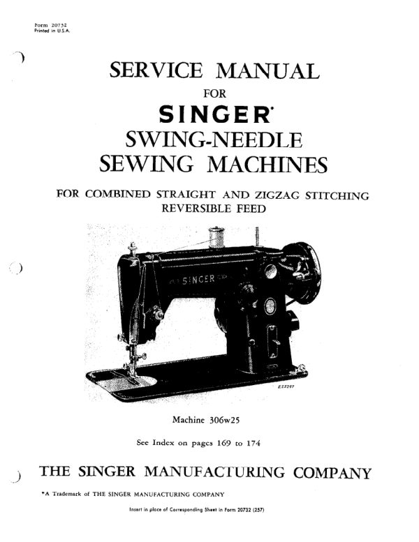
SingerPDF
Singer 206K25, 206K43, 306, 319, and 401 Service
Service manual
174 pages · EnglishRead →
SingerPDF
Singer 221 & 222 (Featherweight) Service Addendum
Service manual
6 pages · EnglishRead →
From the ISMACS International. Original publisher and archive notices are retained.
Check the model and edition against your equipment.
PDF verified 2026-10-11.