Sewing machines
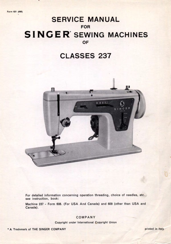
Singer 237 Service — Service manual
Service manual for Singer 237 Service. 36 pages in English. Read the original PDF, download or print a copy without registration.
36 pagesEnglish6.5 MB PDF
Loading your manual…Open PDF directly
Document details
- Brand
- Singer
- Model / document
- Singer 237 Service
- Document type
- Service manual
- Language
- English
- Pages
- 36
- File size
- 6.5 MB
- Category
- Sewing machines
- Document date
- Not specified in catalog
Contents
- Image 00011
- Image 00022
- Image 00033
- Image 00044
- Image 00055
- Image 00066
- Image 00077
- Image 00088
- Image 00099
- Image 001010
- Image 001111
- Image 001212
- Image 001313
- Image 001414
- Image 001515
- Image 001616
- Image 001717
- Image 001818
- Image 001919
- Image 002020
- Image 002121
- Image 002222
- Image 002323
- Image 002424
- Image 002525
- Image 002626
- Image 002727
- Image 002828
- Image 002929
- Image 003030
- Image 003131
- Image 003232
- Image 003334
- Image 003433
- Image 003535
- Image 003636
Search available document text
Find a term, then jump to its page in the original PDF. Image-only pages may not be searchable; check the PDF for exact wording and diagrams.
Page 1 · Read text
Form 631 (666)
          SERVICE MANUAL
               FOR
   SINGER SEWING MACHINES
                   OF

           CLASSES 237


                                                        IN GEF


            For detailed information concerning operation threading, choice of needles, etc..
           see instruction, book:

           Machine 237 - Form 608. (For USA And Canada) and 609 (other than USA and
            Canada).

                       COMPANY

                                  Copyright under International Copyright Union

* A Trademark of THE SINGER COMPANY                                                      printed in Italy
View original page 1Page 2 · Read text
PROPERTY OF THE SINGER COMPANY


This is a private and confidential communication to and for the use of only the em-

ployees of The Singer Company, and its affiliated companies. Reproduction, sale,

distribution, or publication thereof to the public is forbidden.
View original page 2
Page 3 · Read text
DESCRIPTION OF MACHINES 237

  For straight stitch and zig zag manual stitching.      Control panel. This panel contains the Trade Mark,
                                             machine class number, stitch graduations (in stit-
  Foot Power (Machine 237/1)                                             ches per inch and length of stitch in millimeters)
   Electric power (Machine 237/3)                       indications for needle position lever and indica-
                                                    tions for bight control lever, which controls the
 Lock stitch.                                    width of the zig zag or ornamental stitch up to a
                                     maximum of 4 mm. Drop Feed
                                                      Numerically graduated thread tension device.  Adiustable reverse feed.
                                       Maximum stitch length - 6 per inch. Needle Catalogue 2020 (15 × 1) - Threaded from
 left to right.                                   Needle bar stroke - 1.228 inches.
  Central bobbin oscillating transverse shuttle.        Presser bar lift - .290 to .300 inches.
  Shuttle race latch which permits quick opening    Bed - 14.5/8 inches long - 7 inches wide.
 of the shuttle race for easy removal of shuttle.
                                                 Working space at right of needle - 6.7/8 inches.
 Semi-automatic bobbin winder attached to arm
 and protruding through the plastic top cover.       Speed - up to 1100 R.P.M.
  Needle bar and presser bar do not project above     Weight of machine: 28 Ibs.
the top of the machine.

         PREPARATION OF MACHINE FOR INSPECTION
  Before any extensive inspection is undertaken to    NOTE: UNDER EXTREME CONDITIONS- IF
 find causes of faulty operation machine should be   GREASE OR DIRT HAS BECOME TACKY, AP-
 thoroughly cleaned. and oiled.                PLY VARSOL TO ALL OIL HOLES AND RUN
                                       MACHINE. CONTINUE APPLYING VARSOL UN-
 Remove all lint, dust or foreign particles from                                                TIL MACHINE RUNS FREELY: WIPE DRY AND
machine.                                    APPLY OIL. AFTER COMPLETE OILING, WIPE
  Wipe machine clean and dry.              MACHINE DRY.
   Oil the machine as instructed below and on page 5.

                       LUBRICATION


                                                                    Fig. 2 Front View - Oiling.
View original page 3Page 4 · Read text
LUBRICATION (continued)


               0д


           CLEAN
            BETWEEN
            TENSION DISCS

Fig. 3 End View Oiling.                                   Fig. 4 Top View Oiling.


                               Fig. 5 Bottom View Oiling.
View original page 4Page 5 · Read text
TO SET PRESSER FOOT AT CORRECT HEIGH1


  IMPORTANT: Unless presser foot is set at correct
 height, attachments for these machines may not
 function properly on presser bar.

  CAUTION: Throat plate must be flush with bed
 slide while setting presser foot height.


CHECK:

  "Raise presser bar lifter to bring presser foot to
 highest position. Needle clamp must clear presser
 foot. Lower presser bar if interference occurs"

   Test alignment of presser foot to feed slots in
 throat plate and to feed. Fig. 7 shows presser foot
 in correct alignment. Height and alignment of
 presser foot must be set at the same time.

  "When presser bar is lowered, presser foot must
 rest squarely on throat plate",


SETTING:

1. Loosen set screw A, Fig. 6.

 2. Raise or lower presser bar, as required.

 3. Align presser foot and securely tighten set
  screw A.                                                       Fig. 6 Setting Presser Foot at Correct Height


                                 Fig. 7. Presser Foot in Alignment with Slots in Throat
                                    Plate and with Feed Dog.
View original page 5Page 6 · Read text
TO SET FEED DOG AT CORRECT HEIGHT


                  Fig. 8. Feed Adjustments                   Fig. 9. Stitch Length Regulator Set for 12 Stitches.

PREPARATION:                           SETTING:
 1. Set stitch length regulator for 12 stitches per    1. Turn hand wheel over toward you to bring feed
    inch, as shown in Fig. 9.                    dog to its highest position.
 2. Turn hand wheel over toward you until feed dog    2. Loosen clamping screw B, Fig. 8.
     is at its highest position.                            3. Move crank C up or down as required to bring
                                                    feed dog to correct height.
                                                           4. While maintaining this setting, securely tighten
                                                  clamping screw B.
  HECK:
  With feed dog at its highest position, slightly                STRAIGHT EDGE
 less than a full depth of teeth should project above
 top surface of throat plate, as shown in Fig. 10.         ASSAAAAAAAAA
                                                         -- FEED DÕE
                                                            .040 to
                                                            .043 inch                  THROATPLATE

                                                                        Fig. 10. Feed Dog at Correct Height.

     TO SET FEED DOG LENGTHWISE IN THROAT PLATE SLOTS

                                     CHECK:

                                                    While turning hand wheel over toward you, feed
                                            dog should come as close as possible to front of
                                                        throat plate slots without striking throat plate.


                                      SETTING:
                        Fig. 11
                                                        1. Loosen nut D, Fig. 11.
PREPARATION:                                                        2. Turn eccentric stud E, moving feed dog toward
  1. Set feed dog at correct height, as instructed above.       front or rear, as required.

 2. Set stitch length regulator for 12 stitches per     3. While correct setting is maintained, securely
    inch, as shown in Fig. 9.                               tighten nut D.
View original page 6Page 7 · Read text
TO SET FEED DOG SIDEWISE IN THROAT PLATE SLOTS
           AND TO ELIMINATE END PLAY OR BINDING
      OF FEED ROCK SHAFT AND FEED LIFTING ROCK SHAFT


                                  Fig. 12. Setting Feed Dog Sidewise and Adjusting for
                                end Play or Binding.


 PREPARATION:

    Set feed dog at correct height, as instructed on
page 6.


                                   CHECK FOR BINDING OR END PLAY OF FEED
 CHECK:                                   LIFTING ROCK SHAFT.

  Feed dog should be located centrally (along the
bed in reed siots or throat plate.


  SETTING: (See fig. 12)                      SETTING:

  1. Loosen set screws F which hold cylindrical cen-      1. Loosen set screws K which hold cylindrical cen-
     ters G and H for feed rock shaft R in position.       ters I and feed lifting rock shaft S in position.
  2. To position feed dog toward either left or right    2. Lightly tap cylindrical centers I equally upon
    loose screws F making the side shift of the feed      Feed Lifting Rock Shaft S so that it rides freely
     rock shaft using a metal hammer or drift.            without end play or binding.
  3. When feed dog is centralized in throat plate     3. Then securely tighten set screws K.
   make certain the cylindrical centers G and H
    hold feed rock shaft R freely without end play
     or binding.

  4. Then securely tighten screws F.
View original page 7Page 8 · Read text
TO CHECK FOR BINDING OR END PLAY OF     position. Fit needle, Cat. 2020, size 18, remove
OSCILLATING ROCK SHAFT.                         throat plate and arm top cover.

SETTING: (See Fig. 12 page 7)               CHECK:
1. Loosen set screws L which hold centers M and     The shuttle point should come as close as pos-
   oscillating rock shaft T in position.                   sible to the small groove side of the needle without
 2. Move centers M equally so that shaft T rides     touching the needle. Clearance betwee needle and
                                                             front edge of shuttle race cap should be approxi-    freely without end play or binding.
                                                  mately .010 inches, see fig. 13A. 3. Securely tighten set screws L.

TO CHECK FOR BINDING OR END PLAY OF           010"
OSCILLATING SHAFT.
                                                         inches
 SETTING: (See Fig. 12 page 7)

 1. Open shuttle race gate and remove shuttle.
 2. Turn hand wheel over toward you untilset
   screws V appear.
3. Loosen set screws V in collar 0 and adjust
    collar O until oscillating shaft N turns freely                                                                           Fig. 13A. Position of shuttle Race
   without end play or binding.                    CAP in relation to the needle.
4. Securely tighten set screws V.
                                         SETTING: (see fig. 12 pag. 7, fig. 30 pag. 20 and
NOTE: CHECK EACH SETTING AFTER TIGHT-        fig. 13A.)
ENINGSET SCREWS OR LOCK NUTS, AND      1. Loosen exagon head screw T6, fig. 30 pag. 20.
RE-ADJUST IF NECESSARY.                                                        2. Adjust shuttle race frame J until correct posi
Should shafts L and M still bind, check feed bar       tion in relation to the needle is obtained.
  Q for end play or binding.                        3. Securely tighten screw T6
                                                      4. Loosen screw Z, fig. 13A
SETTING:
                                                       5. Adjust position of shuttle race cap and tigh-
  Remove feed rock shaft assembly as instructed      ten screws Z.
 on page 17 and adjust feed bar screw centres as      6. Replace throat plate and arm top cover.
 instructed on page 18.

                                 TO CHECK THREAD CLEARANCE BETWEEN
                                     SHUTTLE CUSHION SPRING AND SHUTTLE.

                                     PREPARATION:
                                                        1. Remove bobbin case.
                                                       2. Turn hand wheel over toward you until needle
                                                   bar is at its highest position.

                                    CHECK:
                                                With needle bar at its highest position, clearance
                                               between shuttle and shuttle cushion spring (spring
                                                      not compressed) should be equal to the thickness
                                                            of a paper match folder or a business card.

                                      SETTING:
         TO CLOSE                            1. To close gap, lightly tap outside of shuttle
                                                         driver X, Fig. 13, with a brass drift.
           Fig. 13. To adjust Thread Clearance.               2. To open gap, lightly tap inside of shuttle driver
                                                X, Fig. 13 with brass drift.
TO CHECK THE POSITION OFTHE NEEDLE
 IN RELATION TO THE SHUTTLE AND SHUTTLE   TO CHECK FOR BINDING OR END PLAY OF
RACE CAP.                            SHUTTLE RACE FRAME ASSEMBI Y

PREPARATION:                         PREPARATION:
  Set m/c for straight stitching and centre needle    1. Set machine for straight stitching.
View original page 8Page 9 · Read text
2. Set needle lever position in center lever position.      3. Loosen set screws Z in collar Y and adjust col-
                                                                 lar until oscillating shaft turns freely without
 SETTING: (See Fig. 12 pag. 7)                       binding or end play.
 1. Open shuttle race gate and remove shuttle         4. Securely tighten screws Z.
 2. Turn hand wheel over toward you until two set     5. Check position of needle in relation to the shuttle
   screws Z appear.                             and if necessary readjust as instructed above

             TO SET THE TAKE-UP SPRING


                 K1


             Fig. 14. Setting the Stroke.                                    Fig. 15.                            1.16.
                                                     Stud Set Screw.          "O'• Setting.


 TIMING THE STROKE: (See Fig. 14)

 The take-up spring should complete its action and
 be at rest against stop B1 as eye of needle enters
fabric.
 Loosen screw C1 and move slack regulator D1
 down (to the right) to complete take-up spring        DECREASE         INCREASE
 action earlier (shorter stroke); move regulator D1
 up the left) to complete take-up spring action later                                               G1
 (longer stroke).
  Then tighten screw C1.                        A1                                                       F1

                                                                            Fig. 17. Setting the tension
SETTING THE TENSION:
                                    down in a vertical position. This is the normalTension on take-up spring should be just sufficient
                                                       setting. to take-up slack of needle thread until point of
 needle reaches fabric.                           To increase tension on take-up spring, move spring
                                            end F1 right to next groove of sprocket to G1; toLoosen stud set screw E1, Fig. 15 and remove
                                             decrease tension, move spring end left to next entire tension assembly. Turn numbered dial to
                                              groove."O" releasing tension. Hold tension assembly so
 that component parts are in position shown by      Replace assembly, draw take-up spring so that
 dotted line in Fig. 17. Place spring end F1 in groove         it rests on regulator stop B1, Fig. 14, and recheck
 of sprocket G1 so that take-up spring A1 hangs      tension. Tighten stud set screw E1, Fig. 5.

            TO ADJUST NEEDLE THREAD TENSION

 This machine is equipped with a one-cycle dial     At "O' there should be a barely perceptible
tension which, when set correctly, offers a barely   amount of tension, as otherwise, difficulty may be
perceptible tension at "O' to a maximum at the     experienced when sewing satin stitching and other
 end of one complete turn of thumb nut.           forms of closed ornamental stitching.
View original page 9Page 10 · Read text
ADJUSTMENT:                                        revolution of the thumb nut. If the pull is too strong
    Pull thread through tension discs to test amount      for a minimum tension, press in dial J1 to disen-
  of tension on thread at "O" position. At this point   gage pin K1 on nut from dial, and reset pin in next
  there should be a slight pull on the thread to     hole to left of previous setting. Repeat this adjust-
  indicate there is minimum tension which gradually    ment until a point of no tension is reached. Then
  increases with the turning of thumb nut H1 to the     advance one hole to right to give minimum tension
  right, providing a full range of tension with one     at zero position.


           TO SET NEEDLE BAR AT CORRECT HEIGHT


                                     CHECK:

                                                          1. Turn handwheel over toward you until needle
                                                       bar is at its lowest point. The upper timing mark
                            UPPER                                             on needle bar should now be in line with the                                  TIMING
                          MARK          bottom of the needle bar frame (upper needle
                                                       bar bearing).
                         LOWER
                                  TIMING        2. Continue turning handwheel over toward you
                          MARK              until lower timing mark on needle bar is in line
                                                          with bottom of needle bar frame (upper needle
                                                        bar bearing).

                                          The shuttle point should now be directly in
                                                                 line with the needle and a short 1/8" above the
                                                        top of the needle eye.


                                       SETTING:

                                                        1. With needle bar at its lowest point, loosen set
                                                   screw L1, Fig. 18 and raise or lower needle bar,
                                            as required.

                                                              2. Wile maintaining correct needle bar height, make
                                                            certain needle bar stays correctly turned, i.e.,
                                                   needle clamp and thumb screw be parallel with         Fig. 18. Setting Needle Bar at Correct Height.
                                                     the front edge of the bed, and securely tighten
                                                          set screw L1.PREPARATION:
 1. Remove throat plate.                                  3. Replace throat plate.

  2. Remove face plate.                                   4. Replace face plate.


            CHECK FOR BINDING OR END PLAY
                  OF UPRIGHT SHAFT


PREPARATION:                                        2. Press down upon the crank H6 against casting
                                                            while pressing the upright shaft lower crank (from
 1. Remove arm top cover.                                                    underside of machine) up against casting.

                                                            3. Securely tighten exagon head screw T6.
SETTING: (See Fig. 30 pag. 20):
                                                         4. Check position of needle in relation to shuttle
1. Loosen exagon head screw T6 one quarter     as instructed at page 8 and it necessary re
     (1/4) turn.                                        adiust.


                                      10
View original page 10Page 11 · Read text
TO ELIMINATE END PLAY OR BINDING IN THREAD TAKE-UP MECANISM


                                   V2


                           Fig. 19.. Thread Take-up Mechanism to Eliminate End
                            Play or Binding in Thread Take-up Mechanism.


PREPARATION:                                         that it is Tightened against flat on take-up crank
                                          Q1.
 Remove Face Plate and Top Cover.
                                                               5. Check that take-up lever R1 moves freely without
                                                   binding. SETTING: (See Fig. 19).
                                                            6. Turn hand wheel over toward you. Loosen clam- 1. Turn hand wheel toward you until take-up crank
                                                      ping screw in hole 01, adjust hinge pin P1 un-    set screw M1 is accessible from top of machine.
                                                                                                                   til take-up lever link S1 moves freely and securely
  2. Loosen Hinge pin set screw 01.                     tighten clamping screw 01
                                                       tighten clamping screw 01.
  3. Loosen set screw M1 and adjust take-up crank
   Q1 until there is a minimum of end play in take-up     7. Check that take-up mechanism moves freely
   lever R1 without binding.                             without binding.
 4. Firmly secure set screw M1, making certain     8. Replace face plate and arm top cover.
View original page 11Page 12 · Read text
REMOVALS AND REPLACEMENTS
               NEEDLE THREAD TENSION


                 N4
                                                          P4
                           TENSION
                        STUD


                         R4
                                     04

                                      Fig. 20. Needle Thread Tension Assembly.


 REMOVAL: (See Fig. 20).
 1. Turn thumb H1 to left (anticlockwise) until
   "O" on numbered dial J1 stops at center line
   on indicator 04, Fig. 20.
 2. Press in dial J1, separating pin K1 in thumb
    nut H1 from hole in dial J1, unscrew thumb nut
   H1 and remove it from tension stud.

 3. Remove stop washer Q4 spring P4 and tension
    indicator 04 from tension stud.

4. Then, as a unit, remove tension disc assembly
   (thread guard N4, tension discs M4, and take-up
    spring A1).
                                                          N4
5. Remove tension releasing pin R4.
                                                                       Fig. 21.
NOTE: IT IS NOT NECESSARY TO REMOVE       Tension Disc          Stop Fig.Washer22. and
                                                          Assemoly.              Tension SorinaTENSION STUD FROM MACHINE. IT IS SHOWN
REMOVED IN FIG. 20. TO ILLUSTRATE COM-
PLETE ASSEMBLY. SEE PAGE 9 FOR INSTRUC-
TIONS ON REMOVAL OF TENSION ASSEMBLY
AS A UNIT.                                           5. Replace indicator 04, Fig. 20 with open side
                                                     facing out and with plus (+) and minus (-)
REPLACEMENT:                                     signs at top.
1. Make certain that tension releasing pin R4 is       6. Hold these assembled parts against shoulder
                                                             of stud and place tension spring P4, Fig. 20,     in place as shown in insert, Fig. 20.
                                             so that the half coil at front is in the lower
 2. Place tension discs M4 on thread guard N4 as         position, on tension stud.
   shown in Fig. 21.
                                                               7. Place stop washer Q4 on stud so that its exten-
  3. Pass take-up spring eyelet T1 under thread guard        sion points upward away from machine on
   with coilsof spring above tension discs as         tension stud as shown in Fig. 22.
  shown in Fig. 21.
                                                           8. Replace numbered dial J1 so that stop on in-
 4. Align coils of spring with holes in discs and        side of dial is to right of stop washer Q4
    place this assembly on tension stud as shown        extension
     in insert Fig. 20 Extension S4 of thread guard
                                                          9. Push dial J1 to compress spring to facilitate   N4 enters hole provided in machine head.
                                                      replacement of thumb nut H1.
 NOTE: TAIL F1, FIG. 21. ENTERS ONE OF THE     10. Replace thumb nut H1 carefully guiding pin
GROOVES IN REAR OF TENSION STUD (SEE      K1 into one of the holes in dial J1.
INSTRUCTIONS "SETTING THE TENSION" ON
 PAGE 9).                                            11. Adjust assembly as instructed on page 9.


                                           12
View original page 12Page 13 · Read text
REMOVALS AND REPLACEMENTS
   HAND WHEEL AND CLAMP STOP MOTION FLANGED BUSHING


                         Х1

                                 Fig. 23. Hand Weel and Bobbin Winder Assembly.


REMOVAL: (See Fig. 23)                              1. Replace the new clamp stop motion flanged
                                                 bushing X1 on the arm shaft, ensuring that the
1. Disengage belt from hadwheel or remove hand                                               cone point on screw Y1 fits into the Vee groove
  attachment.                                          22 on the arm shaft.
 2. Remove stop screw U1 from clamp stop motion                                                        2. While holding the arm shaft against the front  screw V1.                                                       bearing face adjust flanged bushing X1 against
3. Remove clamp stop motion screw V1, washer         ist bearing face, until the arm shaft rotates
  W1 and hand wheel from arm shaft.                  freely with minimum end play.
                                                         3. Securely tighten set screws Y1 and Z1.
IF IT IS FOUND NECESSARY TO RENEW     4. Replace hand wheel.
 CLAMP STOP MOTION FLANGED BUSHING X1,
CONTINUE AS FOLLOWS:                         5. Replace washer W1.
                                                              6. Replace clamp stop motion screw V1 and tighten.
4. Loosen set screw Y1 (cone point) and set screw
  Z1 (flat point).                                      7. Replace stop screw U1 in clamp stop motion
                                             screw V1 and tighten.
 5. Remove clamp stop motion flanged bushing X1
   from arm shaft (if necessary using an extractor).
                                       NOTE: IF STITCHING MECHANISM DOES NOT
REPLACEMENT:                          RELEASE OR DRIVE WHEN CLAMP STOP MO.
                                    TION SCREW V1 IS ADJUSTED, REMOVE
 ITEMS 1 TO 3 APPLY ONLY IF CLAMP STOP   SCREWS U1 AND V1. REMOVE WASHER X1,
MOTION FLANGED BUSHING HAS BEEN RE-   ROTATE  180°AND REPLACE. REPLACE
NEWED.                          SCREWS V1 AND U1.

                    BOBBIN WINDER
REMOVAL:                             REPLACEMENT:
1. Remove arm top cover.                            1. Replace bobbin winder.
2. Remove screw A2 and washer B2.                 2. Replace screw A2 and washer B2

                                                         3. Replace arm top cover.


                                     13
View original page 13Page 14 · Read text
REMOVALS AND REPLACEMENTS
                 STITCH LENGTH REGULATOR


REMOVAL: (See Fig. 25) ,

 1. Remove hand wheel as instructed on page 13.
      (It is not necessary to remove the clamp stop
   motion flanged bushing).

 2. Remove top cover, remove screws which fasten
    front panel to machine arm, remove front panel
    retaining rings (inside of arm) see fig. 24.
 3. Move regulator lever to lowest position.

 4. Remove large hinge screw C2, Fog. 23, page 13,
                                                                     Fig. 24. Inside arm front panel retaining rings
    with its washer from arm casting.

 5. Pull entire regulator, with front panel out of ma-
   chine arm.


REPLACEMENT:

 1. Install regulator in arm, making certain that re-
   gulator fits on slide block of feed forked connec-
   tion, as shown in Fig. 25.
                                                       SLIDE
 2. Replace large hinge screw C2, Fig. 23, page 13              BLOCK
   with its washer through arm casting and into
   regulator.
 3. Position indicator plate and fasten to arm with
   screws, and retaining rings (inside of arm)
    Fig. 24.

 4. Replace hand wheel as instructed on page 12.


                                                    STITCH LENGTH
                                                 REGULATOR

                                                                         Fig. 25. Stitch Length Regulator.


               FEED LIFTINg ROCK SHAFT

REMOVAL: (See Fig. 12 page 7).              REPLACEMENT:
 1. Loosen set screws K and withdraw cylinder cen-      1. Install feed lifting rock shaft in reverse order of
  tres 1.                                          removal.
 2. Remove feed lifting rock shaft S, by sliding rol-     2. Adjust as instructed on page 7 ensuring that
    ler out of feed bar fork, and rock shaft fork       feed bar bears fully on roller, and rock shaft
   over lifting cam on oscillating rock shaft fork over       fork on lifting cam.
     lifting cam on oscillating rock shaft T.                                                            3. Check feed dog height as instructed on page 6.


                                           14
View original page 14Page 15 · Read text
REMOVALS AND REPLACEMENTS
                     V2 N     L 22 G2 D2 F2 ER


                              Z D
                                                 Fig. 26

                   OSCILLATING ROCK SHAFT

 REMOVAL: (See Fig. 26)                    REPLACEMENT:
1. Turn hand wheel over toward you until oscilla-     1. Install in reverse order of removal, ensuring
    ting rock shaft fork is inside arm casting.            that connecting rod F2 is in its correct position
                                                                                   i.e., it is not displaced too far towards either end
2. Loosen nut D2 and remove stud E2 from connec-                                                          of machine, causing binding on armshaft or   ting rod F2.                                                              oscillating rock shaft bearing.
 3. Loosen set screws L and withdraw centers M.                                                          2. Check as instructed on page 8.
 4. Remove oscillating rock shaft T.

                    OSCILLATING SHAFT

 REMOVAL: (See Fig. 26)                                2. Slide through shuttle race and replace collar O.
1. Remove shuttle. and leave gate open.              3. Continue sliding shaft on through bed bearing.
 2. Turn hand wheel over toward you until oscilla-    4. Replace collar Y.
    ting shaft crank, drive pin G2 is in a convenient
                                                        5. Slide through upright shaft crank slide block.    position for removal.
                                                          6. Assemble new oscillating crank H2 (see inset) 3. Drive out pin G2.
                                                ensuring that slide block fits into oscillating
4. Turn hand wheel over toward you until oscil-      rock shaft fork.
    lating shaft crank set screw 12 appears (see
                                                          7. Check as instructed on page 8.    inset, Fig. 26).
                                                          8. Replace shuttle and close gate. 5. Loosen set screw 12.

 6. Loosen oscillating shaft collar set screws V and
  V2.                            TO TIME OSCILLATING SHAFT.
 7. Loosen rear oscillating shaft collar set screws Z      1. Remove throat plate and face plate.
  and Z2.
                                                        2. Turn hand wheel over toward you until lower
 8. With brass drift tap oscillating shaft N away       timing mark on needle bar is in line with bottom
   from oscillating shaft crank H2.                                                             of needle bar frame upper needle bar bearing.
9. Once clear of crank H2, shaft N should withdraw     3. Turn oscillating shaft until point of shuttle is
    easily through shuttle race frame and bed bearing.        directly in line with needle.
  At same time remove collar O. and Y.
                                                      4. Securely tighten set screws 12 on crank H2,
REPLACEMENT:                                    ensuring that crank slide block is fitted evenly
                                                           into oscillating rock shaft fork.1. Insert oscillating shaft N (with shuttle driver)
   in shuttle race frame.                               5. Check timing and readjust if necessary.


                                     15
View original page 15Page 16 · Read text
REMOVALS AND REPLACEMENTS
                   SHUTTLE RACE FRAME


 REMOVAL: (See Fig. 26)                                 2. Adjust approximately only at this point and com-
                                                            plete adjustment after step 3.
 1. Remove oscillating shaft as instructed on page
  15.                                                 3. Replace oscillating shaft in reverse order of
                                                           removal.
 2. Remove shuttle race frame J.
                                                            4. Control needle position in relation to the shuttle
                                                     race cap and readjust as instructed on page 8REPLACEMENT:
1. Install shuttle race frame in reverse order of
   removal

              FEED ROCK SHAFT ASSEMBLY


PREMOVAL: (See Fig. 26)                  REPLACEMENT:
 1. Remove oscillating shaft as instructed on page 16.     1. Install feed rock shaft R with feed assembly
                                      U in reverse order of removal, ensuring that feed
2. Remove shuttle race frame as instructed above.      bar fits on roller.
3. Loosen nut D and remove eccentric stud E from                                                       2. Check as instructed on page 7 for end play,
  feed fork L2.                                                       binding and feed dog position.
4. Loosen set screws F and withdraw centers H
  and G.                               NOTE: IF REQUIRED, TO MAINTAIN CORRECT
                                           POSITION OF FEED FORKED CONNECTION L2
5. Remove feed rock shaft R with feed bar as-                                                                       I.E., IT DOES NOT BIND ON FEED CAM OR FEED
  sembly U.                             REGULATOR, ADJUST FEED BAR U ON FEED
                                 ROCK SHAFT R AS INSTRUCTED ON PAGE 17.

                                                             3. Check feed bar settings as instructed on page 7.

                                                            4. Replace shuttle race frame as instructed above

                                                               5. Replace oscillating shaft as instructed on page 15.
View original page 16Page 17 · Read text
REMOVALS AND REPLACEMENTS

                                       D2


                     M2    M2   02

                                                          Fig. 27.


                 FEED BAR ASSEMBLY


 REMOVAL: (See Fig. 27)                                 3. It is necessary to position feed dog to left, loosen
                                               screw centre N2 and tighten screw centre 02.
 1. Remove feed rock shaft assembly as instructed                                           To position feed dog to right, loosen screw
  on page 16.                                                       centre 02 and tighten screw centre N2. Adjust
2. Loosen lock nuts M2, withdraw screw centres      screw centres 02 and N2 until feed bar moves
   N2 and 02 and remove feed bar assembly U from       freely without end play or binding, and tighten
  feed rock shaft R.                                lock nuts M2.
                                                         4. Check feed bar for end play or binding.
REPLACEMENT:
                                                            5. Install feed rock shaft assembly only, and check
 1. Replace feed bar assembly on feed rock shaft,                                            as instructed on page 7.
   and initially tighten screw centres N2 and 02
   equally upon feed bar.                                6. Replace shuttle race frame as instructed on pa-
                                       ge 16.
 2. Install feed rock shaft assembly only, and check
   as instructed on page 7.                                7. Replace oscillating shaft as instructed on page 15.
View original page 17Page 18 · Read text
REMOVALS AND REPLACEMENTS
                CRANK CONNECTING ROD


PREPARATION:

   Remove arm top cover and turn hand wheel toward
  front of machine, until crank connecting rod is at
  its lowest position.                                                  Q2

REMOVAL:
1. Loosen nut D2, Fig. 27, page 17, and remove
    screw stud E2, Fig. 27, page 17.
 2. Remove cap screws P2 and remove capQ2.
    (Note position by shape of boss X, Fig. 28, for
    replacement).

 3. Remove connecting rod through bottom of ma-
    chine.                                       CRANÉCTING ROD

REPLACEMENT:
                                                                              Fig. 28. Crank Connecting Rod.
 1. Insert connecting rod into arm, with stud oil
   hole facing front, from bottom of machine,
   between oscillating rock shaft and front side of
   arm casting, so that it fits around bottom of
   arm shaft bearing.
                                                             3. Replace screw stud E2, Fig. 27, page 17, enga-
 2. Replace cap Q2 over top of arm shaft bearing,                                                      ging connecting rod with oscillating rock shaft.
    facing direction as on removal, and fasten with
  screws P2.                                            4. Replace nut D2 and tighten securely.


                FEED FORKED CONNECTION


REMOVAL: (See Fig. 27, page 16)             REPLACEMENT:

  1. Remove arm top cover.                              1. Insert feed forked connection L2 into arm, from
                                               bottom of machine so that the slide block fits
  2. Loosen arm shaft counterbalance and feed cam                                                                  in the stitch length regulator.
    set screws.
                                                            2. Replace eccentric stud E, engaging feed forked
3. Slide arm shaft counterbalance and feed cam                                                  connection with feed rock shaft.
   towards face plate to free forked connection.
                                                           3. Replace feed cam on arm shaft and tighten set
4. Loosen nut D, and remove eccentric stud E                                                screw into the proper slot.
    disengaging feed forked connection L2 from feed
   rock shaft R.                                         4. Replace arm shaft counterbalance and tighten
                                                      set screw in the proper hole on feed cam.
5. Remove feed forked connection L2 from arm,
    through bottom of machine.                           5. Set feed dog lengthwise as instructed on page 6.
View original page 18Page 19 · Read text
REMOVALS AND REPLACEMENTS
                     NEEDLE BAR


REMOVAL: (See Fig. 29)

1. Remove arm top cover.

 2. Remove face plate.

 3. Remove needle bar thread guard.
                                    U2
 4. Remove needle clamp.
 5. Loosen screw L1 and push needle bar from
   bottom removing it from top of arm.


REPLACEMENT:
 1. Insert needle bar from top sliding it through
   needle bar bracket upper hole, bearing hole,
  needle bar connecting stud and needle bai
   bracket lower hole.

 2. Replace needle clamp.

 3. Replace needle bar thread guard positioning it
    in needle bar slot then, using a screwdriver, fit
     it in proper seat.

 4. Adjust needle bar height as instructed on page 10.

5. Securely tighten screw L1.

 6. Replace face plate and arm top cover.                                          Fig. 29


                    PRESSER BAR

                                      REPLACEMENT:
REMOVAL: (See Fig. 29)
                                                           1. Install presser bar assembly in reverse order of
 1. Remove face plate, presser foot, thumb screw        its removal
   and top cover.
                                                          2. Replace presser foot on presser bar.
2. Remove pressure regulating thumb screw T2.
                                                         3. Adjust presser foot at correct height and align
 3. Remove extension pin U2 with spring from top       foot with feed dog slots in throat plate, as in-
   of machine.                                                          structed on page 5.
 4. Loosen screw A and remove presser bar from                                                         4. Securely tighten screw A.
   machine.
                                                          5. Replace face plate and arm top cover.


                                19
View original page 19Page 20 · Read text
REMOVALS AND REPLACEMENTS
              NEEDLE BAR VIBRATING BRACKET


                                           U6

                 Q1

 REMOVAL: (See 'Fig. 30)

 1. Remove arm top cover, face plate, presser foot
   and presser bar thumb screw T2.
 2. Loosen screw 6.

 3. Loosen screws C6 and D6.

  4. Pull out bushings F6 and E6 respectively from
    top and bottom of machine.                                                 D6
  5. Remove extension pin U6 from top of machine.

 6. Remove needle bar vibrating bracket assembly.
 7. Remove retaining ring B6.                                                                                                                                     • E6

  8. Loosen clamping screw L1.

  9. Remove needle driving arm S6.
                                                                      Fig. 30. Needle Bar Vibrating Bracket.
10. Remove needle bar.

11. Remove presser bar with guide bracket without
    loosening clamping screw V2.
                                                          4. Adjust needle on throat plate as instructed on
                                            page 22.
                                                           5. Adjust needle position in relation to the shuttle
                                             and shuttle race can as instructed on page 8 REPLACEMENT:

 1. Assemble needle bar, presser bar and needle
    bar driving arm on needle bar vibrating bracket.
                                         NOTE: PRESSER BAR LOWER BUSHING MUST  2. Assemble needle bar vibrating bracket.
                                    BE PUSHED UP UNTIL ELIMINATION OF END
  3. Set needle bar at correct height as instructed on   PLAY, WITHOUT BINDING OF NEEDLE BAR
   page 10.                               VIBRATING BRACKET.


                                      20
View original page 20Related documents and language editions

SingerPDF
Singer 101-1
Parts list
42 pages · EnglishRead →
SingerPDF
Singer 101-1, 101-2, 101-3, 101-10, & 101-11 Adjusters
Service manual
48 pages · EnglishRead →
SingerPDF
Singer 101-2, 101-3, 101-10 & 101-11
Parts list
136 pages · EnglishRead →
SingerPDF
Singer 101-3 & 101-11 Adjuster's
Service manual
20 pages · EnglishRead →
SingerPDF
Singer 115-1 & 115-2 Parts List
Parts list
38 pages · EnglishRead →
SingerPDF
Singer 128-8 Parts List
Parts list
20 pages · EnglishRead →

SingerPDF
Singer 15-86 & 15-87 Parts List
Parts list
61 pages · EnglishRead →

SingerPDF
Singer 15-88, 15-89, & 15-90 Parts List
Parts list
63 pages · EnglishRead →
SingerPDF
Singer 201-1, 201-2, 201-3, 201-4, & 1200-1 Adjuster's
Service manual
72 pages · EnglishRead →

SingerPDF
Singer 206K25 Service
Service manual
28 pages · EnglishRead →
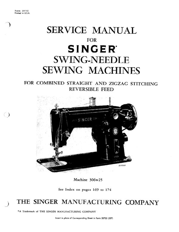
SingerPDF
Singer 206K25, 206K43, 306, 319, and 401 Service
Service manual
174 pages · EnglishRead →
SingerPDF
Singer 221 & 222 (Featherweight) Service Addendum
Service manual
6 pages · EnglishRead →
From the ISMACS International. Original publisher and archive notices are retained.
Check the model and edition against your equipment.
PDF verified 2026-10-11.