Sewing machines
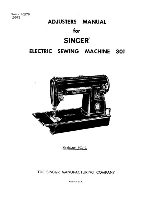
Singer 301 Adjusters — Service manual
Service manual for Singer 301 Adjusters. 12 pages in English. Read the original PDF, download or print a copy without registration.
12 pagesEnglish0.9 MB PDF
Loading your manual…Open PDF directly
Document details
- Brand
- Singer
- Model / document
- Singer 301 Adjusters
- Document type
- Service manual
- Language
- English
- Pages
- 12
- File size
- 0.9 MB
- Category
- Sewing machines
- Document date
- Not specified in catalog
Search available document text
Find a term, then jump to its page in the original PDF. Image-only pages may not be searchable; check the PDF for exact wording and diagrams.
Page 3 · Read text
- 3-
  20579


                             ADJUSTERS MANUAL

                                 for
                      SINGER

                       ELECTRIC SEWING MACHINE 301


                      TO REMOVE AND REPLACE MOTOR

  To remove motor:

 1. Tilt machine back on its rear
      side
  2.  Remove bottom cover plate
  3.  Remove motor hold down plate by
      removing screw from
 4. Remove two electricalsleeveleah.con-

      terminals
 5. Slide motoroutFigotoward1   you,rock-
      ing motor from sideto side to
      facilitate removal

       Fig• 1shows grease tube X3 as
         appears on motor of machines
      now leavingthe factory. In the                            X3
     past,some machines have been
           out with motor grease tube
      located diametrically opposite                                     Fig. 1.Removing and
      the one illustrated in Fig. 1.          Replacing Motor


                             To replace motor:
                                    Make sure that wire Dhe Fig. 2 1s
                               properly located in order to prevent
                               motor from rubbing or chafing against
                             Wire.  Fig. 2 shows wire properly
                                Located around and under cylindrical
                                     and upand behind three
                                        19 Fi% 2
                             1. Slide motor into position, turning
                                    hand wheel slightly to ensure
                                  proper gear mesh.  Be sure motor
                                    is properly positioned by pushing
                                   motor clockwise until motor butts
                                   against casting as shown by curved
                        D4                                    row in Fi
                        2.  rit electricai sieve connectior
Fig. 2. Location of Wires
       around Motor         3.  Replaceo22g. motor1 overholdterminalsdown plateC, andFig.                                   bottom cover plate
View original page 3Page 4 · Read text
- 4-

                TO REMOVE AND REPLACE SINGERLIGHT: SOCKET

 To remove SINGERLIGHT socket:

      Remove topcover of machine
      Remove oil

      unscrew two wireconnectors and
      untwist wires
 3. Remove sINGaRLIC lap shade and

     Remove
     Remove 1lght sockot and Its wire:                                  -E3
       by passing wires down through
      rubber grommet E, Figs. 3 and 4


                                               Fig. 3.  Removing
                                               SINGERLIGHT Wires


                              To replace SINGERLICHT socket:

                                    Reverse above procedure.  See
                               wiring diagram on page 12 for correct
                               wire connections.    Fig. 4.  Removing
    SINGERLIGHT Socket


                    TO ADJUST HEIGHT OF PRESSER FOOT

          IMPORTANT:
                      Etachmentspresser forfootthisheightmachineis toowillhighnot f.or too 1o
               properly on the presser bar.


To adjuitaurossor foot to correct


                                                                 F3
     face plateset screw G3, Fig. & behind
3. Move oresser bar up or down,              G3
              until the bottom of

          thetop surface of the
4.Tightenthroat plate, We sets m


                                                                   .295"


                                               Fig. 5.  Adjusting
                                              Presser FootHeight
View original page 4Page 5 · Read text
.
                        TO TIME ROTATING HOOK

 I. Remove presser foot and throat plate.  (Feed dog has been removed
                and I for clearer view, butit need notbe removed
      to time rotating hook.)
 2. Turn hand wheel            you until lower timing mark de Fig.
      on needle bar   aligned with lower end of the needle
      at I on upward stroke of needle bar
   If needle bar      correct hoight and in position described In
      paragraph 2 above,and if hook is correctly timed,
          should be atcenter of needle and approximately      above
      eye of needle as shown                     of rotating hook is
         broken     and bolin caserost biase is moved around
            finger      out of the way In Flg. I for clearer view
      of needle and pointof hook.


                                  13


   2410%6
                        E21420
                                                                                          £21916

 Fig. 6. Timing Rotating Hook       Fig. 7. Relation of Needle to
                                             Rotating Hook

 If hook is not correctly timed,

1. Remove bottom cover plate
2. Loosen two setscrews t, Fig. & in
      gear at right hand end of hook
     shaft
3. Turn hook until its point is in
      proper relation to needle as
      explained above and shown in

                            8, main-4. TightentainingtwoproperscrewsbacklashIt neto ensure
      correct gear mesh

NOTE:  Hub of gear should never bear
       against face of bushing at
         Figu                       Fig.8.  Adjusting Gears
                                              For Correct End Play
5.  Replace bottom cover plate
View original page 5Page 6 · Read text
- 6 -

                    TO SET NEEDLE BAR AT CORRECT HEIGHT

        To set needle bar at the correct height, the rotating hook must


                    With the needle bar in this position,

     minsbushingmark shouldas shownbe atin K,alignmentFig. 6. with the lower end of the needi


   the screw I.


        The needle bar bushing is accurately
   no adjustment.   If its position has been disturbed,set at the factory and needs
   and wheel over toward you until the point of the hookhowevel the upwerd

  stroke of the noedle bar, is at the center of the needle and approsen

                                                  aligns with the
                                        Then tightenthe set screw Q.


         TO SET NEEDLE BAR,NEEDLE BAR BUSHING AND ROTATING HOOK
                         WHEN ALL ARE OUT OF TIME

       I. Adjust the needle bar bushing until the recess in the bushing is
       visible through the set screw hole for
  2. Tum the hand wheel over toward you until the newl fir d'at the


   un a can no, go one i tou to the hookof thepeteneedlede bar)ae the


 9. Turn1ts thelowesthandpositionwheel over toward you until the needle bar reaches
10. Loosen   e needle bar bushing set scre
      bushing up or down until the bottom of
                                             e the bushing altons wit
      theand uppertightentimingthe screwmark ong  the needle bar as shown at I, Fig. 6,
View original page 6Page 7 · Read text
Shaft replacementshould be made without disengaging teeth
  gears.    following                                        gears will
 keep in mesh during replacementthe instructionsof   on the previouscorrectlocationpage,     of
  shaft with relation to rotating hook is determined as follows:

 1. Set and tighten screw        of collarso that left hand end of

 2. Take outend play by setting counterbalance
      P1g. 9, pushing collar and counterbalance toward each other, ano

 3.

           while keeping hub of hook against shaft collar, tighten screw
                                            tighten screw on other side
                          right hand end of shaft with clearance
      between gear hub and bushing, and tighten
4. Be sure to time rotating hookas instructedtwoon screwspage  M. Fig. &

             The gears of this machine are properly meshed when machine
 IMPORTANT:      leaves factory and they should not be disturbed for any reason.

                    TO REMOVE AND REPLACE HAND WHEEL

                                           02*2
     c2
  B2

                                              B2
                               H2                                 E2/128


       E2I624

                Figs. 11 and 12. Hand WheelAssembly

To remove and disassemble hand wheel:

 I. Remove small screw Y, stop motion nut Z and clamp washer A2,


     Lift hand wheel gear spring D2 off stud E2 in hand wheel


To reassemble and replace hand wheel:

     fits over middle


3. Replace snap ring B2 so that it


                                          remove washer A2, rotate it
View original page 7Page 8 · Read text
- 7-


                  TO REMOVE AND REPLACE ROTATING HOOK
                        (without affecting timing)


                              Io remove rotating hook:
                             1. Remove presser foot, throat plate
                                    and bottom cover plate
                             - Loosen two screws, only one of which
                                     Is visible at R, Fig. 2 in hub of
                               hook
                             3. Remove rotating hook from shaft


                             To replace rotating hook:
                                      I. Turn hand wheel over toward you un-
                                    il flat on hook shaft is visible

                        2.                      so that set
                                             on sameside
                               bub as
                                   flat of hook shaft
      S                 3.       with hub of hook against shaft
                               collar, tighten screw R which en-
   Fig. 9. Removing and            gages flat, and then tighten second
  ReplacingRotating Hook         screw on hub
 and Replacing HookShaft     Replace bottom cover plate, throat                      4.
                                    plate and presser foot


                    TO REPLACE ROTATING HOOK SHAFT

1.Remove presser foot, throat plate,
     bottom cover plateand rotating
     hook
 collarscollar, andand screwserenis har
         counterbalance so that the

    Loosen    screws M. Fig.
4:  Remove motor hold down plate and
     motor
5.  Unscrew and move two pin terminal
                       thatit
      tiì not interfere wit replace-
     ment of new rotating hook shaft
6.  Use new shaft (with flats at
     left end) to push out oldshaft
     from right to left.  Insert new
      shaft through opening in casting
    from which twopin terminal was
     removed. Be sure thatend of
     shaft with twoflats (for rotat-
                                        Fig. 10. Iwo Pin Terminal
     shaft collar T        counter-        Removed For Hook Shaft
     balance screw U) is at theleft             Replacement
View original page 8Page 9 · Read text
- 9 -


                    TO ADJUST FEED DOG HEIGHT
 1. Setstitch regulator at 8 stitches
     per inch
 2.  Turn hand wheel over toward you until
      feed dogis at Its highest point
                         and turn3. Loosen       crew P3 to
      teeth  I reed doe project .043'
      above throat plate as shown at
4. Keepingscrew73,Fig• 13  P3 In position with
       screwdriver,tighten nut N3,
     Fige 14
                                  LIUM


                                             F1g• 13.  Correct
                                        Height ofFeed Dog

          TO ADJUST FEED DOG LENGTHWISE IN THROAT PLATE SLOTS

 1.  Check feed dog heightas described above
 2.  Remove       cover plate, motor holddown plate and motor
    Loosen nut
    With
     positionan or toF18.a Wurnto dooccentric stud P2 to adjust lengthwise
 5. Whenproper adjustment hasbeen obtained, holdeccentric stud P2
      in position with a screwdriver whiletightening nut N2

NOTE:  On Machinesof Class 301 having a split rock shaft, this adjust -


     then tighteningclamping screw 22.


      N2
                P2               R2      Q2

Fig. 14.  Adjusting Feed Dog      Fig- 15.  Adjusting Feed Dog
   MachineHaving Standard            (Machine Having Split
     Feed Rock Shaft)                    Feed Rock Shaft)
View original page 9Page 10 · Read text
- 10 -

                        TO REGULATE FEED THROW-OUT

      To prevent rotating.hook fromstrikingfeed
 tive (fordarning,                             when feed is inopera-
 ulatedas describedembroidering,below:       etc.), feed throw-out must be reg-


                                                            U2-


      Fig. 16.  RegulatingFeed                                   Fig. 17.  Regulating Feed
       throw-Out ThumbScrew                                     Throw-Out Stop Screw

 1.
     Checkplatefeedinstructeddog heightonandpagelengthwise position of feed dog in throat
 2.  Set stitch lengthto longest
     Turn hand wheel
4:  Turn feed           toward you until feed is at its lowest point                                                          (inwardly)
              screwdriver if necessary,                                                              tightened
          nachine back on its rear side and remove botton      plate
    Set feed throw-out                                                     clearance between
       ood throw-out lever 12, Pig. I and stop screw  1s from. 002"
7.Replace bottom covor plate


               TO ADJUSI ARM SHAFT FOR CORRECT END PLAY


1. Remove top cover, and loosen
    setscrew         in     collar  V2, Fig. 18
2. Push collar and crank W2,
             toward each other
     andand tishton set screw V?
3. Replace top cover

CAUTION: Be sure that top cover
     Is properly aligned so that
     It does not bind against
    presser barthumb screw,
    when replacing topcover
                                                                  E21423  W2         V2
                                    Fig. 18. Adjusting Arm
                                      Shaft For Correct End Play
View original page 10Page 11 · Read text
- 11.


                     TO ADJUST GEARS FOR CORRECT MESH
 1.  Remove top cover from machine, and remove oil shield fromabove
      the connecting rod
  2. Remove                               from connecting rod
      Loosen
 4:  Tighten screw Y2 and replace andconnectingadjust rodto propercap, oilgearshieldmesh and
       top cover of machine


    E21428      Z2

 Fig. 19. Removing Connecting                                   Fig. 20.  Adjusting Gears
             Rod Cap                 To Correct Mesh

      This adjustment can
  connecting rod cap
                             through oil hole Z2.  Then insert

 ment to correct meshand intoretightenhole IZ,screwlooseny2. screw Y2, make adjust-


                   TO REMOVE AND REPLACE BOBBIN WINDER


 Io remove and disassemble bobbin      winder:

    Remove hand wheel
   Turn
      counterclockwise
     bobbin winder assembly
      comes off the machine


                                                           D3

                                 Fig. 21. Bobbin Winder Assembly

To reassemble and replace bobbin winder:

1.  Fit parts together
2. Replace on machine by fitting•derscrewindicatedAs     in fig.                                             n machine and then tiphi
                                 that right angle projection B3
3. Replaceor seehandcanewheela fitted into hole a in casting of machine
View original page 11Related documents and language editions

SingerPDF
Singer 101-1
Parts list
42 pages · EnglishRead →
SingerPDF
Singer 101-1, 101-2, 101-3, 101-10, & 101-11 Adjusters
Service manual
48 pages · EnglishRead →
SingerPDF
Singer 101-2, 101-3, 101-10 & 101-11
Parts list
136 pages · EnglishRead →
SingerPDF
Singer 101-3 & 101-11 Adjuster's
Service manual
20 pages · EnglishRead →
SingerPDF
Singer 115-1 & 115-2 Parts List
Parts list
38 pages · EnglishRead →
SingerPDF
Singer 128-8 Parts List
Parts list
20 pages · EnglishRead →

SingerPDF
Singer 15-86 & 15-87 Parts List
Parts list
61 pages · EnglishRead →

SingerPDF
Singer 15-88, 15-89, & 15-90 Parts List
Parts list
63 pages · EnglishRead →
SingerPDF
Singer 201-1, 201-2, 201-3, 201-4, & 1200-1 Adjuster's
Service manual
72 pages · EnglishRead →

SingerPDF
Singer 206K25 Service
Service manual
28 pages · EnglishRead →
SingerPDF
Singer 206K25, 206K43, 306, 319, and 401 Service
Service manual
174 pages · EnglishRead →
SingerPDF
Singer 221 & 222 (Featherweight) Service Addendum
Service manual
6 pages · EnglishRead →
From the ISMACS International. Original publisher and archive notices are retained.
Check the model and edition against your equipment.
PDF verified 2026-10-11.