Film cameras
Voigtlander BESSA 6x9 - another User manual
User manual for Voigtlander BESSA 6x9 - another. 19 pages in English. Read the original PDF, download or print a copy without registration.
19 pagesEnglish6.9 MB PDF
Loading your manual…Open PDF directly
Document details
- Brand
- Voigtländer
- Model / document
- Voigtlander BESSA 6x9 - another
- Document type
- User manual
- Language
- English
- Pages
- 19
- File size
- 6.9 MB
- Category
- Film cameras
- Document date
- Not specified in catalog
Search available document text
Find a term, then jump to its page in the original PDF. Image-only pages may not be searchable; check the PDF for exact wording and diagrams.
Page 1 · Read text
t      www.butkus.us
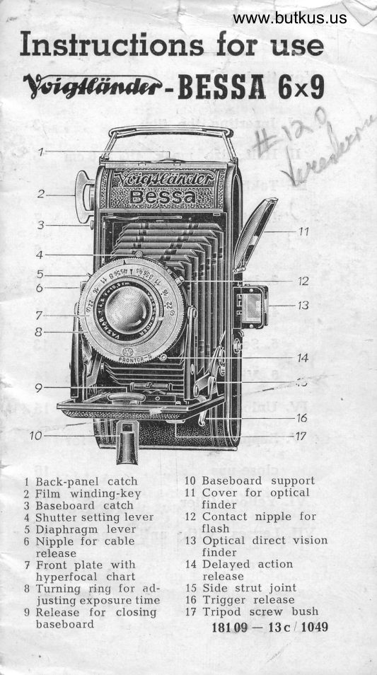
Instruclions for use
                 6x9W-BES$A
               t


  4
   5
   6                                                      12


 1 Back-panel catch         Baseboard support 2 Film winding-key              10n Cover for optical
 3 Baseboard catch            finder
 4 .Shutter setting lever       12 Contact nippie for
 5 Diaphragm lever             flash
 6 Nipple for cable          13 Optical direct vision
   release                       finder
 7 Front plate with           14 Delayed action
  hyperfocal chart            release
 B Turning ring for ad-      15 Side strut joint
   justing eXposure time      16 Trigger release
 9 Release for closing      t7 Tripod screw bush
   baseboard                      l8l 0S   13c / lO49                                         -
View original page 1Page 3 · Read text
t!                          www.butkus.us
ti
        I. fnserting the fiknrri
    Any  31/s X 2L/E ins. film, including
     the 620 spool, can be used with the
     Bessa. The film is inserted in the
    camera in weak daylight or (when
     in the open) in the shade (shade of
     the body is sufficient).


      Open the back of the camera after
       pushing sideways the button 1 (pic-
        ture 2).
      )  Put the empty spool in the top film
       chamber, after pulling out the film
       winding-key 2 as far as it witl go.
      The slot in the spool must face the
       k"y, while the other end engages
      on the pin 18.
      Replace the top film protecting
       cover, push in the film winding-
     key and tuin until the catch 20
                                                  3
View original page 3Page 4 · Read text
engages the slot, when the spool
    will turn with the key"


3. Place the new filnn spool in the
   lower film chamber; do not tear off
   the paper band until this is done.
  Hold the protecting paper firmly
  and swing in the metal cover.
4, Pull out the protecting paper (fig. 4)
  and insert the point into the wide
   slot in the empty spool. The co-
  loured side of the paper must lie
   uppermost.
5. Press the film key firmly inwards
  and turn twice, until sure that the
  paper is being moved on. It must
  run exactly between the flanges of
   the empty spool and must not over-
   lap on either side.
6. Close the back of the camera. The
  round aperture at the top must en-
  gage in the groove on the film key.
4
View original page 4Page 5 · Read text
www.butkus.us
 v. Open the film windows by turning
   the milled knob, between the win-
   dows, to the right.
 B. Wind the film key evenly until you
   see in the lower red film window
   first several hands, then several
   dots and finally the number 1. Now,
  the film windows should be clo-
  sed again by turning the milled
  knob to the left as far as the back
    stop.
If. The Small Size Picture Device
enables 16 small pictures size
2rlE X tsls ins. to be taken. Fig. 5
clearly shows how the grooved tongue
must be inserted in the picture frame.


First insert the mask at the bottom,
then bend gently and let it spring in
at the top. It must then lie absolutely
View original page 5Page 6 · Read text
flat. When closing the camera back,
the upper film window, which is clo-
sed with full size 6 X 9 cm, opens


automatically. When using the half
size mask, the numbers of the pic-
tures on the protecting paper must be
adjusted twice,
l st picture No. t in the lower film
    window,
2nd, picture No. 1 in the upper film
    window,
3rd picture No. 2 in the lower film
    window,
4th picture No. 2 in the upper fiim
    *indow.
The optical finder also has a mask for
small size pictures, mounted on the front
lens portion. This must be raised for
all small size exposuies (seeparaIII/6).
6
View original page 6Page 7 · Read text
www.butkus.us
      III. Taking the pictures.
    Opening the camera. press the but_
    ton 3 and evenly pult down the open
    end of the baseboard until the stiuts    snap in at 15.
   And closiRg. Press the catch g in the
     direction of the camera body (pic-     ture 6). The baseboard can now- be
    closed without effort.
     1. Adjust the Focus
   The feet focussing scale is engraved
   round the edge of the froni lens
   mount 21. Turn the front lens by the
                                     against    milled lirg and set the focus    the mark, as shown in fig. 7. oo L  in-
     finity, i. e. anything ovei 100 feet.


                                      Digitally signed by mike butkusmike                DN: cn=mike butkus,
                             o=orphancameras, ou=29,
                               email=mike@butkus.org, c=USbutkus            Date: 2019.09.01 12:22:44 -04'00'


   Snapshot adjustments are: V at 12 feet   and O at 50 feet. If you use as small
  an aperture as F/tt, the sharp zone
View original page 7Page 8 · Read text
(see cipher 3) will extend from B feet
 to 16 feet with focus set at V  and
 from X6 feet to oo with focus set at O.


The following rule should  therefore
be noted:
For snapshots close-up, set at v.
For snapshots at 16 feet or longer
  range, set at O.
Use the aperture of F/tl.

2. Stop Adjustment
You already know that the dia-
phragm increases the depth of focus,
while at the same time it reduces ihe
lens aperture and thus lengthens the
exposure time. (The smaller the stop
{aperturel, the higher the stop num-
ber.) The stop numbers of the Bessa
B
View original page 8Page 9 · Read text
www.butkus.us
      are calculated in such a .way that
      each smaller stop requires double the
       time of exposure of the preceding one.
     The stop lever is denoted by 5 in
         fig. B.

        3. Depth of focus
       Hyperfocal chart (at the back of the
        camera):
          If you set the focus to a certain range,
      say t2 feet, then not only that point,
      but a certain surrounding zone will
     be sharp. At 25 feet and F14,5, for.
       example, everything between 19 feet
      and 36 feet will be sharp. This zone

f


       increases as the aperture diminishes.
     At 25 feet and Fltt, it extends from
      14 feet to 102 feet.
View original page 9Page 10 · Read text
To read the depth-of-focus table, find
the aperture in the left verticai co-
lumn (e. g. tri8) and on the correspon-
 ding horizontal line there appears,
under each distance marking, the
various distances covering the zone
of sharpness (depth-of-focus) e. g., at
F/B when the lens is focussed at 6 feet,
everything is sharp between 5 feet
and 7 feet.


With Bessa 6X9 with Prontor S the
hyperfocal chart is no longer on the
camera back but is engraved on the
front p1ate. The actual range of ';he
depth of focus for each stop can im-
mediately be read, after focussing.
Example: At 12 feet and stop 5,6 the
depth of focus extends from 10 feet
to 15 feet or by focussing on 20 feet
and with stop 16 from 10 feet to oo
(infinity).
10
View original page 10
Page 11 · Read text
www.butkus.us
      4, Shutters
    The shutter must be set before each
      exposure, also with B and T (the latter
     with Prontor only).
     Compur-Rapid shutter must be set by
     pressing the lever 4 to the right, tha
                           pressing thisi    Prontor S shutter by     lever to the left.


                           -r2


    The figures represent fractions of se-
     conds, e. g. 5 means I/sth of a second,
    100 means rl:r;o sec. and so on. Ii
    necessary, the shutter can be set bet_
   ween the values e. g. r/zr sec. between
    50 and 100. Exception: Do not set bet_
   ween 10 and 25 as well as with higher
    speeds than 1/roo sec. For the ,,T,, ad_
    justment (Prontor S only), the shutter
    opens when the trigger is first pressed
   and closes when it is pressed a se-   cond time.

                                                   11
View original page 11Page 12 · Read text
For the "B'r adjustment, however, the
shutter remains open as long as the
pressure on the release lever is


maintained. The various markings
are set opposite the indication by
revolving the milled ring B. All shuf-
ters are released by pressing down
the trigger 16 (fig. 7), which operates
the release lever.
       adjusting and setting at the_Whenhighest speed of the Compur Rapid
some resistance is encountered, due
to the engagement of a powerful
spring. Turn the milled ring genily
past the tension.
Besides Compur Rapid, the Bessa is
fitted with Prontor S (highest speed 1/z;o                     -addition     sec.), which has, in           a
selftiming device. With Prontor S, as
with all other Prontor shuttefs, d syn-
chronized flash unit may be used. Tfre
t2
View original page 12Page 13 · Read text
www.butkus.us
nipple L2 on the upper part of the
shutter must be connected with a
flash unit and the picture may be
taken as usual. AII speeds of the
shutter from 1/zr sec. to L sec. may be
used with the flash unit.
5. Delayed Action-Release
Compur Rapid: Adjust and set lever
as usual, then push button 24 bacl<
and again set lever 4.
Prontor S: Adjust speed and set shut-
ter as usual. Push lever t4 to the
left.
For all shutters: Release in the usual
manner. The shutter operates only
after the delayed-action mechanism
has run d.own, so that you have about


10 seconds to return to your position.
A slight click indicates that the shut-
ter has been operated
                                         13
View original page 13Page 14 · Read text
For B and T and the maximum speed
 of the Compur Rapid the delayed-
 action release must not be used.

 6. Finder and Release
 When the camera is opened, the op-
 tical finder 13 springs up into p-o_ sition. Use it for preference, since
 shots at eye level will then have the
 most natural perspective.
 Hold the camera as in figs. LL and 12,
 i. e. press it firmly against the face
 and look through the rear lens of the
 finder. The front lens indicates the
 exact angle of view. The whole rim
 of this lens must therefore be vi-
 sible.
For pictures in the half-size , 2Llq, X lble
ins., bring up the small size mask in-
to the frame; this mask is hinged to
the front portion of the finder.
Close the finder by simply pushing
down the cover, do nof iodch th6
lenses.
The essentially practieal trigger re-
Iease on the baseboard, ensniii.g cer-
tain release without vibration, witt
be found very helpful.
To avoid shaky pictures, press down
the. trigger until it encount-ers a slight
resistance, i. e. be "ready to fire., as
with a rifle, hold your breath and
evenly pull back the trigger. practise
t4
View original page 14
Page 15 · Read text
www.butkus.us
      this until it goes smoothly, and in
     time you will be able to take 1/r sec,
     and even L/z s.ec. exposures by hand.
                           i':'     N. B--   Get used to tilrning on i,tn-
     mediately after every exposure, as
     otherwise double exposures will be
      frequent.


,  13
     IV. Unloading
       L. After making the last exposure,
       tqrn on until the protective paper
        is no longer visible in the lower
        film window
      2. Open the back of the camera, hold
       the end of the paper securely and
        carefully turn on the film key a
       short distance. The film will thus
        . be wound tightly; loosely wound
        films are susceptible to light, while
      on ,the other hand films wound too
        tightly will become scratched.
                                               1{
View original page 15Page 17 · Read text
www.butkus.us
Adhere accuratelY to the distance,
measuring from the lens. Shots taken
with the Focar lens show a slight lack
of sharpness with full aperture, parti-
cularly to-
wards the
corners. At
the aperture
F/5.6 or F /B
the  sharP-
ness increa-
ses and at-
tains   the
   normal
standard at
Flt2.s. The
time of ex-
posure re-
mains the
           assame
 when work-                              needsincl without a Focar lens, i' e' it
*Et"iV n" Iengthened in. propgtion
l;-th" aperturei When using u.Fo:-11                                                    f inder does not grvelens the view
 the exact size of the actual picture' A,s
 fioure L4 shows, the actual picture wrlr
 ilE litpr"""o towards the camera-edge                                and                     camera              between      ti;" (distance[o                       by 1/a (dis-                       Llrlz") ot-       not under o6;ect
 tance between-12")    camera and object not
 ;;a;       of the view finder field'
 VI. Yellow Filter
                                   for ob- Yellow filters are indispensable
 iai"i"g  attractive landscaP€s' since
                                          T7
View original page 17Page 18 · Read text
they bring clouds into view. As a ge-
neral rule, coloured objects should not
be taken without yellow filters, since
only with their use can the colour va-
lues of the various shades be correctlv
reproduced.
Voigtliinder filters are ground as care-
fully as lenses from spectroscopically
tested glass. They are firmly mounted
on the camera lens mounts.
'Ihe times of exposure are lengthened
as follows:

     FiIter G1                   lr/z    2 X                              -    Filter G2        2    X                       -4

The Correct Time of Exposure
The modern amateur film with a
speed of approx. 27-280 Scheiner
(17/t00 DIN) has an extensive latitude
of exposure so that yeu need not be
extremely careful when exposing.
However, as general rule you should
always keep in your mind: you will
get the best pictures with an expo-
sure which is also sufficient for the
shadows !  Theref ore never give too
short a time of exposure.
VII. Cleaning coated lenses
When looking obliquely at these len-
ses you notice a bluish-violet gleam.
18
View original page 18Page 19 · Read text
www.butkus.us
      This indicates that they are "eoated"
          i. e. fitted with
              "anti reflection layers".
    The AR layers obviate leflection of
      light rays as a result of "counter-
      light" i. e. they reduce it to a mini-
    mum; at the same time they increase
      the brilliance of the pictures and the
      transmission power of the lens.
    Even uncoated lenses require very
     i     careful treatment; the outer surfaces     of lenses with AR layers should be
      treated with especial care. These lay- n        ;    ers are very hard, but they are ex-
      tremely thin (app. 1/ro ooo mm.).
     The lens must be cleaned with a fine I       hair brush or a very soft cloth. Grease
     and oil stains may be removed by
 ;    carefully touching with prlre alcohol

        :      or ether.

   l


                  -->\
                               *-r*It            Et
View original page 19Related documents and language editions
VoigtländerPDF
VOIGTLANDER BESSA L - RE-RELEASE BOOKLET
Product booklet
5 pages · EnglishRead →
VoigtländerPDF
Voigtlander BESSA 6X9
User manual
20 pages · EnglishRead →
VoigtländerPDF
Voigtlander Bessa - model 2
User manual
13 pages · EnglishRead →
VoigtländerPDF
Voigtlander Bessa 6X6
User manual
5 pages · EnglishRead →
VoigtländerPDF
Voigtlander Bessa II
User manual
30 pages · EnglishRead →
VoigtländerPDF
Voigtlander BESSA II 6x9 Gebrauchsanleitung
User manual
33 pages · GermanRead →
VoigtländerPDF
Voigtlander Klein-Bessa
User manual
25 pages · GermanRead →
VoigtländerPDF
Voigtländer BESSA-R2A / BESSA-R3A
User manual
97 pages · GermanRead →
VoigtländerPDF
another Voigtlander Klein-Bessa - Gebrauchsanleitung
User manual
24 pages · GermanRead →
VoigtländerPDF
Voigtlander BESSA-R2M, R3M
User manual
23 pages · German, SpanishRead →
VoigtländerPDF
Voigtlander BESSA - T
User manual
110 pages · German, Spanish, ItalianRead →
VoigtländerPDF
Voigtlander BESSA R2S / R2C
User manual
23 pages · German, Spanish, ItalianRead →
From the M. Butkus archive. Original publisher and archive notices are retained.
Check the model and edition against your equipment.
PDF verified 2026-10-10.