Film cameras
Contax RTF 540 User manual
User manual for Contax RTF 540. 45 pages in English. Read the original PDF, download or print a copy without registration.
45 pagesEnglish12.1 MB PDF

Loading your manual…Open PDF directly
Document details
- Brand
- Contax
- Model / document
- Contax RTF 540
- Document type
- User manual
- Language
- English
- Pages
- 45
- File size
- 12.1 MB
- Category
- Film cameras
- Document date
- Not specified in catalog
Search available document text
Find a term, then jump to its page in the original PDF. Image-only pages may not be searchable; check the PDF for exact wording and diagrams.
Page 3 · Read text
You have just purchased the  f inest and the most profes-
                                                   sional electronic flash unit on the market today, and the
                                                world's first portable flash unit to offer stroboscopic or
                                                 multiple flash on a single frame. The RTF 540 employs
                                                thyristorized "energy-saving" circuitry for automatic
                                                  flash cut-off at the proper moment and greater battery
                                                             life. lt features a top guide number of 40 (ASA 100 in
                                                 meters), a choice of three f-numbers during automatic
                                                  operation, and 4-way guide number selection on manual.
                                             Moreover, the RTF 540 was designed with ease of ope-
Contents:                                            ration in mind. Incorporation of a unique built-in electro-
Real Time Flash System            .4          magnetic shutter release and the capability of mountingDescription of Parts.              .6                                                                 camera allows optimum con-Specif ications                                    . 10         to the right side of the
"Motorized" Flash Photography       .12          venience when used with the motor drives. And thanks
How to Mount the Real Time Flash                 to an interlocking feature which controls the shutter to
 540 Unit                                  ."t4           release only after the capacitor is fully charged, correct  RTF 540 + Camera               .14   RTF 540 + Camera + Real Time                 exposure can be guranted everytime -- a new threshold
   Winder (RTW)                  .18        which does away with exposure worries in both single-
  RTF 540 + Camera + Professional                 frame and "motorized" flash photography.
   MotorDrive(PMD) ....            .22                                        There is also a swivel flash head for 90o vertical andPower Source                      .26
Operating the Control Panel   .         .34         18Oo horizontal auto-bounce flash, an optional sensor
Auto Flash Photography. .   .         .38           holder unit for off-camera flash on auto, an overheating
Manual Flash Photography.           .50          control system with warning lamp, a wide-angle panelWide Panel                        .56                                          and others.Multiple Flash.                     .58Bounce Flash                      .62         These are just some of the features of the world's most
Close-Up and Daylight Flash.          .64          advanced electronic flash unit. Welcome to the world of
Using the RTF 540 with Other                     "Real Time Flash Photography." Camera Brands.                   .66
Precautions                       .66
RTF External Sensor Holder          .68
RTF Slave Unit   .                   .72
View original page 3Page 4 · Read text
www.butkus.us


O Real Time Flash 540
O RTF Bracket
O RTF External Sensor
   Holder 100/500
@ nff Sync-Release Gord
O nf f Slave Unit
@wiue Panel
O Rf f Color Panel
@ Cable Switch 30/1 00/300
   /1000
O RTF Power Pack
O Winder Battery Case
(D RTW Ni-Cd Pack
@)RTW Charging Adapter
GD Ni-Cd Battery Charger
O RTF 510V Battery Pack                                              ol
(D RTF AC Power Unit
          g'

                                                                                       ffilII                              (Erd                   d.              ffi
View original page 4Page 7 · Read text
O Reflektor
 @ Sensor
 @ Sensoreinheit
 @ Versch   I uBausl<iseknopf
 @ Synch ro-Auskisebuchse
 @ Ausl<isebuchse
 @ Klemmen-E ntriegelu ngshebel
 @ Klemme
 @ Einrastlocher
 @ K lemmenf ixierschrauben
,\tuwffi)+8?ff xiilixllliil,.r,.,t",
 @ Sperrschalter
 @ Automatik-Priif lampe
 @ Warnsignal
  (9 Pr0fk nopf/Bereitschaftslampe
 @ Blendenanzeige
 @ Leitzahlanzeige
  (9 F  i lmempf ind  I ichkeits-E    i nstel lknopf
  Q0 F  i lmempf indl ichkeitsanzei ge
 @ StromanschluBbuchse
View original page 7
Page 8 · Read text
www.butkus.us


O Winder Support Arm
@ Brace
@ Bracket-Mount Screur
@ Lock Pins
@ Clip-on X-Sync Connector
@ Sync'Release Plug
@ Release Plug
@ wioe Panel


             RTF Bracket
                 RTF-Befestigu ngsschiene
View original page 8Page 11 · Read text
RTF 540 The Real Time Flash 540 System offers a wide variety of accessories to choose from.     +
 However, the true sophistication of this sys'     Gamera
 tem can only be appreciated when the Real
 Time Flash 540 unit is used in concert with
 the motor drive units. Capable of perfectly-
 exposed flash in synchronization with the
 Real Time Winder (RTW) and the Professional
                                            has Motor Drive (PMD), the RTF System ushered in a new era of "motorized" flash     RTF 540 photography. In view of the new applications      + possible with the RTF 540 unit, it has been                                Gamera carefully designed to include a built'in electro' magnetic shutter release to facilitate handling      +
 and shutter access when used with the motor      RTW
 drives.
 O The built-in release makes it possible to
 mount the flash unit on the right side of the
 camera for easy hand-held flash photography
 with the motor drives. Moreover, the flash-     RTF 540 mount clamp is rotatable to enable mounting on the left side of the camera in the standard     +
 manner when the flash unit is used with the     Gamera
                    following            The          alone. camera                            diagrams indicate      +                     mounting:            ways                   of the different
                            PMD


12
View original page 11Page 12 · Read text
www.butkus.us

RTF 540              Das "Real Time"-Elektronenblitzgeriit 540
  +                 stellt lhnen eine breite Spanne an Ausbaumcig-
Kamera           lichkeiten zur Wahl. Die technischen Finessen                     dieses Systems konnen jedoch nur voll ausge-
                   schopft werden, wenn das "Real Time"-Elek-
                    tronengerdt 540 zusammen mit den Motoran-
                   trieben verwendet wird. Durch seine Befdhi-
                  gung zu perfekt belichteten Blitzaufnahmen in
                   Synchronisation mit dem Real Time Winder
RTF 540       (RTW) und dem Profi-Motorantrieb (PMD)
                           fi.ihrt das RTF-System in ein neues Zeitalter  +              der "motorisierten" Blitz-Photographie. InKamera
  +              lichkeitenHinsicht aufdesdieRTFzahlreichen540 wurdeAnwendungsmog-es mit einem
 RTW           eingebauten elektromagnetischen VerschluB-                    ausloser versehen, um die Handhabung und
                   VerschluKauslosung bei Verwendung mit den
                   Motorantrieben zu erleichtern.
          O Durch den eingebauten VerschluBausloser
                kann das Blitzgerdt an der rechten Seite derRTF 540                Kamera fiir bequeme und wohl ausgewogene
                Handhabung zusammen mit den Motorantrie-  +
Kamera         ben befestigrt werden. Die Befestigungsklemme
  +            Weiseist drehbar,an derso linkendaB dasSeiteBlitzgeritder Kameraauf normalebefe-
 PMD             stigt werden kann, wenn kein Motorantrieb
                 verwendet wird. Die folgenden Diagramme
                    verdeutlichen die verschiedenen Befestigungs-
                       arten :
                                                                          13
View original page 12Page 13 · Read text
RTF s4O+Gamera
      Mounts on the Left Side of Camera

   ll  I Attaching the RTF Bracka to the Camera:
  (The bracket's winder support arm is not extended when
  attaching the bracket directly to the camera.)
  Position the bracket-mount screw as shown in the photo
 and screw it into the camera's tripod socket.
 o rhe bracket is designed so as to permit firm roading
 and_rewind while mounted directly to camera. Z Glamp Adiustment:
 As the flash unit mounts on the left side when fixed
  directly to the camera, the cramp may require reversing.
 To reverse the clamp, roosen the two setscrews by gaving
 them several turns with a coin. Then rotate the cramp so
 that it allows the flash unit to mount to left side of the
 camera. The height of the frash head may be adjusted by
 sliding the clamp verticaily arong the giip. nt.r-i.i.ct-
 ing a. suitable position, fix the ctimp in prace oy center-
 ring it with the verticar groove on the grip and tiitrtening
 the two setscrews.


14
View original page 13Page 14 · Read text
www.butkus.us

E lnterlocking the flash unit and bracket:
 Align the lock pins of the bracket with the lock-pin
 holes of the clamp and push both units together until
 the pins click into place.
 l4l RTF Sync-Release Cord hook up:
 Slide the clip-on X-sync connector all the way into the
 camera's accessory shoe as shown in the illustration.
 Then, align the groove of the sync'release plug with the
 flash unit's sync-release socket and insert into place.
 Next, insert the release plug in the release socket of the
 camera.


                                                                           www.btkus.us


r6
View original page 14Page 15 · Read text
RTF s40+Camera+RTW
     Mounts on the Right Side of Camera


                       Bracket to the winder:E Attaching the RTF
 Swing the bracket's winder support arm out as far as it
 will gL and sct the winder between the support arm and
 the brace. Next, screw the bracket-mount screw to the
 lfipod socket at the base of the winder.
 [2] Adjusting the clamp:
 Loosen the clamp setscrews with a coin. Adiust the
 height and position of the clamp so that the flash unit
 mai Ue positioned properly for use in concert with the
 winder. After making adjustments, fix the clamp by
                                                 and centering it with the vertical groove on the grip
 tightening the two setscrews.


18
View original page 15Page 16 · Read text
www.butkus.us

E Interlocking the flash unit and bracket:
Align the lock pins of the bracket with the lock-pin
holes of the clamp and push both units together until
the pins click into place.
4r RTF Sync-Release Cord hook up:
Slide the clip-on X-sync connector all the way into the
camera's accessory shoe as shown in the illustration.
Then, align the groove of the sync-release plug with the
flash unit's sync-release socket and insert into place.
Next, insert the release plug into either the camera's
release socket or the Real Time Winder release socket.
View original page 16
Page 17 · Read text
RTF s4O+Camera+PMD
     Mounts on the Right side of camera


                                                                                              www.butkus.us
Lll Attaching the RTF Bracket to the motor drive:
(The bracket's winder support arm is not extended when
the bracket is attached to the motor drive.)
Position the bracket-mount screw as illustrated, and
insert it into the tripod socket at the base of the PMD
Power Pack. Tighten in place by tuning clockwise.
o When using the PMD Power Pack separately from the
camera, mount the bracket by screwing  it directly to the
lnotor drive's power-pack socket.
[2J RAlust:ng the clamp:
Loosen the clamp setscrews with a coin. Adjust the
clamp so that the flash unit will mount properly for use
in concert with the motor drive. After adiustment,  f ix the
clamp by centering it with the vertical groove on the grip
and tightening the two setscrews.
View original page 17Page 18 · Read text
www.butkus.us

B lnterlocking the flash unit and bracket:
Align the lock pins of the bracket with the lock-pin
holes of the clamp and push both units together until
the pins click into place.
l4l RTF Sync-Release Gord hook up:
Slide the clip-on X-sync-connector all the way into the
camera's accessory shoe as shown in the photo. Then,
align the groove of the sync-release plug with the flash
unit's sync-release socket and insert into place. Next,
insert the release plug in the release socket of the Profes-
sional Motor Drive.


To Disconnect the Flash Unit/Bracket Assembly:
Slide the clamp-release lever toward the grip and separate
the flash unit from the bracket.
View original page 18
Page 19 · Read text
Three power sources are available as optional accessories
 for usi with the RTF 5rl() unit. The most portable of
                                                             size these is the RTF Power Pack which uses AA
 penlight batteries, and also uses the NaCd battery packs
 originally designed for use with the Real Time Winder
 (RTW NiCd Packsl.
 Other power souroes are the RTW 510V Battery Pack*,
 which uses 510V high'voltage battery and the RTF AC
 Power Unit which plugs into a household outlet. Use of
 the RTF Power Pack is explained throughly in this
 manual, and although brief instructions for use of the
 RTF 51OV Battery Pack and the RTF AC Power Unit
 are given in the following section, refer to the respective
  instruction manual for details on operating these.
  * Sold in the U.S. and Canada

 RTF Power Pack (Wittr Power Pack Jacket)
 The power pack is energized by either twelve 1.5V AA
 size penlight batteries (high'performance  alkaline bat-
 teries are recommendedl or two RTW Ni-Cd Packs.
 E Remove the power pack from its jacket.
  [2J Insert either penlight batteries or Ni-Cd packs into
 the battery compartment of the power pack.
                                                   packs r When using the RTW Ni-Cd packs, insert both
  into the battery compartment with the label side facing
 outwards.


26
View original page 19Page 20 · Read text
www.butkus.us

I When using penlight batteries, insert six batteries each
into the winder battery cases in accordance with the
polarity diagrams on the casing. Then, insert the battery
cases, with the diagram sides out, into the battery com'
partment.
13 Reinsert the power pack into its jacket.
Eil etug the power cord into the flash unit's power
socket by aligning the groove properly.
E Turn the power pack's power switch to ON. The
power indicator lamp will simultaneously light to show
that the unit is charging; the lamp will remain on until
the power switch is turned to OFF.
@ I tew moments after the power is switched on, the
flash unit's ready lamp, which is combined with the test
button, willlight to indicate that the unit is ready to fire.
Test the  f lash circuit by pressing the test button.
View original page 20
Page 21 · Read text
!  Bei Verwendung von Mignonbatterien setzen Sie je
 sechs Batterien in die Winder-Batteriemagazine  entspre-
 chend der auf dem Gehduse gezeigten Polung ein. Die
 Batteriemagazine werden nun mit dem Diagramm nach
 auBen in das Batteriefach eingesetzt.
13 Legen Sie den Batteriebehdlter wieder in die Tasche
 zuri.ick.
 El Scfrtiefen Sie das Stromkabel an die StromanschluB-
buchse des Blitzgerdtes an, wobei auf richtige Ausrich-
tung der Fiihrungsnut zu achten  ist.
[5 Stellen Sie den Stromschalter des Batteriebehdlters
auf ON (Ein). Die Stromanzeigelampe  leuchtet auf und
leBt erkennen, daB der Blitzkondensator aufgeladen
wird. Die Lampe bleibt so lange an, bis der Stromschal-
ter auf OFF (Aus) gestef lt wird.
@Wenige Augenblicke nach Betdtigen des Stromschal-
ters leuchtet die Bereitschaftslampe des Blitzgerdtes auf,
wodurch angezeigt wird, daB das Geriit blitzbereit ist. Sie
konnen den Blitzschaftkreis priifen, indem Sie den mit
der Bereitschaftslampe kombinierten Pri.ifknopf drlicken.


                                                     29
View original page 21Page 23 · Read text
RTF 510V Battery Pack
This power source uses a 510V high-voltage laminated
 battery, and four penlight batteries which control the
transistor circuit. After inserting batteries, plug the
 pack's power cord into the power socket of the RTF
540 unit. For other details refer to the RTF 510V Bat'
tery Pack Instruction Sheet.
RTF AC Power Unit
 Plug the AC power unit into a household outlet and
 insert the power-cord plug into the flash unit's power
 socket. For detailed operating instructions refer to the
 RTF AC Power Pack's instructions.


Number of Flashes and Recycling Times             Number of Flashes and Recycling Times
(RTF 510V Battery Pack)                        (RTF AC Power Unit)
 Guide Numbe      40    28    14     7          Guide Number      40    28    14     7 ASA 1@ (ml                            ASA l(X) (m)
 Recycling Time      2sec.   1sec.  0.5sec. 0.2sec.        Recycling Time     4sec.  2sec.  0.Ssec. 0.2sec.
 Nurrber of Flashss  300   500   800   1200       Number of Flashes           indifinite
o Number of flashes was determined by firing
 the unit at 30 second intervals.


32
View original page 23
Page 24 · Read text
www.butkus.us

                                                                                          MAruAL
                                       AUTOTIFI O Auto/Manual Selector                                                         ItIERlto(                                                                                                     (}il (!rF The Auto/Manual selector is used for selecting
                                                                                                         oso u* automatic and manual f lash modes of operation.                                                  Fttr-L [l                                                               1/z When it is set to AUTO, f-numbers will appear in      nffFllUT0                                                H Fl";FXl the number indicatior; when it  is set to            clrE0( wARl{N6                     rnrw) MANUAL, the guide numbers appear in the                                               pil0) Il*LJ guide number indicator.                  t]uTIST@ Interlock Switch
 The interlock switch is unique to the RTF 540
 unit and one of the most important features of
 the Real Time Flash System.
 INTERLOCK "ON"          '  ' When the interlock
 switch is set to ON, the flash unit's built-in
 shutter release will not function until the capa-       €) Auto Check Lamp
 citor is fully charged and the ready lamp comes       This is used to ascertain that the subject  is within
 on. This assures correct exposure each time in       the effective flash range on AUTO. After testing
 both auto and manual modes, and also when the      the  f lash circuit by pressing the test button, the
 motor drive, winder, and interval timer units are       green auto check lamp will light to indicate that
  used.                                             the subject is within effective auto flash range.
  INTERLOCK "OFF"     When the interlock      When the lamp fails to light, camera-to-subject
 switch is set to OFF, the RTF 540 permits the        d istance requires adj usting.
 option of releasing the shutter before or after the   @ Test Button/Ready Lamp
 ready lamp comes on. This setting is used when it     The circuit test button and the ready lamp are
  is desirable to have the flash and motor drive      combined with the Real Time Flash 540 unit.
 units operate precisely at the motor drive or      The button lights in the manner of a ready lamp
 winder's predetermined sequential intervals.          when the unit charged and ready to  f lash.


34
View original page 24Page 25 · Read text
E
To test the flash circuit, merely press the button     to the given guide numbers. (RTW) and (PMD)
after it lights.                                        are the settings where the unit synchronizes for
@ Warning Lamp                                      high-speed operation with the winder and motorWhen used continuously in rapid sequence with       drive units; these correspond to 118 and 1132
the motor drives, or in the MULTI mode, the      output levels respectively. The MULTI setting,
flash unit may overheat. Should this occur, the      used for stroboscopic multiple flash, has equi-
unit will cease to function and the red warning        valent output of the (PMD) setting.
lamp will come on. The lamp will go out when   O F-number Indicator
the unit has sufficiently cooled to operate again.        Indicates the f-numbers which may be used on
@ Output Selector                          AUTO. Choice will vary in accordance with the
The output selector is a multi-functional device     ASA/DlN film speed setting in use. (The f-num-
which controls the output of the unit in the     ber indicator is blacked out during manual
various modes.                                           operation.)
On AUTO:  lt permits selection of one of three   @ Guide Number Indicator
f-numbers which may be used for single-frame      This is used for calculating the lens aperture on
auto flash as well as auto flash with the winder     MANUAL. Flash output increases or decreases in
and motor drive units.                                      relation to the guide number in use. Guide num-
On MANUAL: lt is used to set the guide number.       bers in meters with ASA 100 film are: 40 at
 It also slides further down the groove on      FULL; 28 at 112;14 at (RTW); and 7 at (PMD)
MANUAL than it does on AUTO to permit fast      and MULTI settings. (The guide number indica-
recycling for high-speed operation at preset        tor is blacked out during auto operation.)
motor-drive intervals; and to permit stroboscopic   O  f itm Speed lndex Knob
multiple flash.                                      This is set to correspond with the ASA/DlN film
Output settings: FULL, 112, (RTW) and (PMD)       speed rating of the  f ilm in use. F-number choice
output power settings indicated to the right of     on AUTO and guide number choice on
the guide number indicator window correspond     MANUAL will vary in relation to the film speed
                                                                            sett   i ng.
View original page 25Page 26 · Read text
www.butkus.us


 The Real Time Flash 54{l enables selection of three f-
 numbers ltl11, t15.6 and f 12.8 with ASA 100 film), and
 may be operated at any of the given f-numbers in con-
 junction with the Real Time Winder and Professional
 Motor Drive. Before attempting auto flash photography,
 make sure the sync-release cord and the power cord are
 firmly connectd.
 [l Set the camera's shutter speed to synchronize with
 the flash unit. The Contax RTS and Yashica FR cameras
 synchronize at speeds of 1/@ second and under; for
 other cameras, refer to page 66.
 E Slide the Auto/Manual selector to AUTO.
 CAUTION: The output selector cannot be used at
 (PMD) and MULTI settings when the Auto/Manual  selec-
 tor is qn AUTO. Attempts to force the output selector
 below the (RTW) setting on AUTO may result in
 breakage.


38
View original page 26Page 27 · Read text
E Set the film speed index to correspond with the speed
 of the film in use by sliding the knob. At the same time,
 the corresponding aperture settings will appear in the f-
 number indicator window.

   Film                             f-number   Speed(ASA)
      800          32          16         8
      400          22            11           5.6
      200          16          8          4
      100             11           5.6          2.8
       50          8          4           2
       25           5.6          2.8           1.4

  Flash range    0.5m-3.6m  1.0-7.1m   2.0m-14m
  on AUTO
 l4l pict< out the f-number to suit the flash-to-subject  dis-
 tance and the type of shooting you are doing. Then, set
 output selector to correspond with your choice among
 the three f-numbers in the window.
 o Only set the output selector to f-numbers at one of
 the three indexed click-stop settings.


                                                                         www.butkus.us


40
View original page 27Related documents and language editions
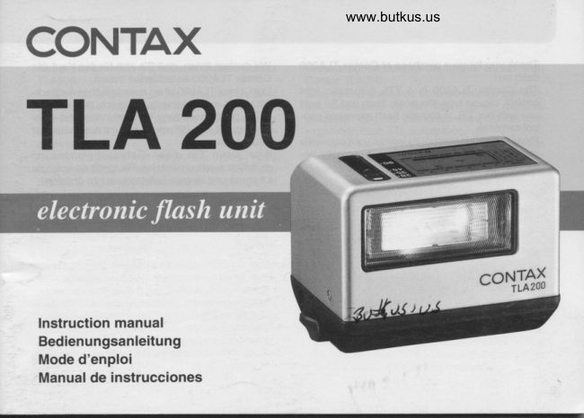
ContaxPDF
Contax TLA 200 Flash
User manual
32 pages · EnglishRead →
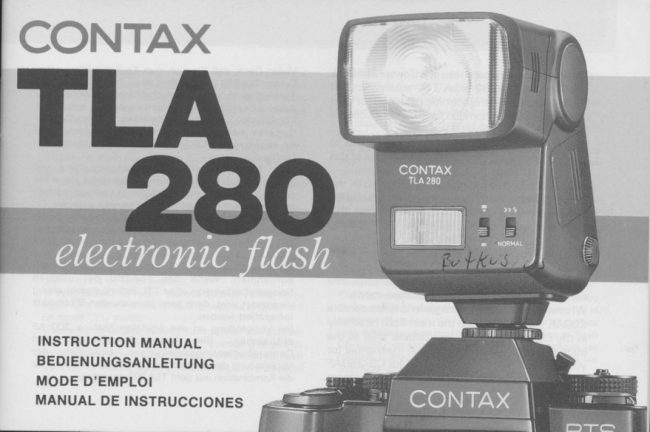
ContaxPDF
Contax TLA 28 flash
User manual
30 pages · EnglishRead →
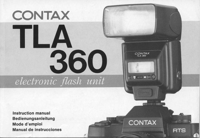
ContaxPDF
Contax TLA 360 flash
User manual
76 pages · EnglishRead →

ContaxPDF
Contax RTF 540
User manual
32 pages · GermanRead →
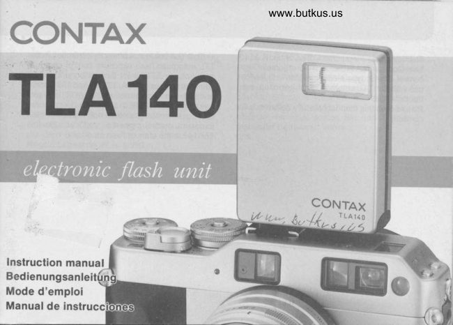
ContaxPDF
Contax TLA 140 flash
User manual
56 pages · German, FrenchRead →
ContaxPDF
Contax Tla 200
User manual
33 pages · German, French, SpanishRead →
ContaxPDF
Contax Tla 280
User manual
34 pages · German, French, SpanishRead →
From the M. Butkus archive. Original publisher and archive notices are retained.
Check the model and edition against your equipment.
PDF verified 2026-10-10.