Camera accessories
Nikon Motor Drive F-36 User manual
User manual for Nikon Motor Drive F-36. 21 pages in English. Read the original PDF, download or print a copy without registration.
21 pagesEnglish1.9 MB PDF

Loading your manual…Open PDF directly
Document details
- Brand
- Nikon
- Model / document
- Nikon Motor Drive F-36
- Document type
- User manual
- Language
- English
- Pages
- 21
- File size
- 1.9 MB
- Category
- Camera accessories
- Document date
- Not specified in catalog
Search available document text
Find a term, then jump to its page in the original PDF. Image-only pages may not be searchable; check the PDF for exact wording and diagrams.
Page 4 · Read text
NIKON MOTOR DRIVE F.36

The Motor  Drive attachment adapts the Nikon F or Nikon F Photomic-T camera
for automatic, sequence or single-frame exposure photography.
Remote control operation  is also possible.   Supplied completely with  a portable
battery case and a 3.3 ft (1 m) long three-core cord.
The Motor  Drive  unit  is factory-adjusted to a particular Nikon  F  or Nikon  F
Photomic-T camera and mav not function when used with other cameras. Consult
your dealer or the manu-
facturer,    if  you  desire
to use  it  in combination
with  other Nikon F cam-
eras.
View original page 4
Page 6 · Read text
It plugs into the battery case outlet terminal.
  Do not leave the tester plugged into the battery case
  any longer than you need, to avoid unnecessary con-
  sumption of the batteries.
O In case any power source is used other than the bat-
  tery assembly described above, the  following  data
   will be helpful.
    Electromotive force :  D.C . 12 V
    Electric current :      0.4 A, approximately
  D.C. rectified from  A.C. can be used so  f.ar as too
  much  ripple  current  is not  produced, which  may
  cause injurious  effects in  the  inside  circuit  cf  the
  Motor  Drive.
  Voltage should by no means exceed 16 V.
o Be careful not  to make a mistake in connection.                          Fig.  4
  Note also that any cord  to be used for  the Motor
  Drive  is of three-core type, as illustrated  in  Fig. 4,
  consisting of three layers ; C  for plus, @ and @ for
  minus connections.
   In connecting or disconnecting the  cord, hold  the
  thick molded end.
View original page 6Page 7 · Read text
TOADING

o Attach the Nikon Motor Unit to the camera body    The Nikon F camera equipped with
   in place of the standard camera back  Fig. 51.     the Motor  I-Jnit accepts a standard film
                                                         lcad, both 20 and 36 exposures, as the
                                                  normal  Nikon  F  camera.  The  film
                                                          perforation, however, should be care-
                                                                  fully  attached to  the notch  on  the
                                                   winding spool and to  the film  drive
                                                     sprocket to prevent the initial surge of
                                                      the motor from  pulling the sprocket
                                                          drive free of the film.
                                                 o  It  is recommended to use the Nikon
                                                                film cassette(mag azine)rather than the
                                                              film cartridge (patronet,since the latter
                                               causes more friction and results in a
                                                     reduction of the driving speed,and also
                                                     depletes the batteries more rapidly.
                                                 o With  the Motor  Drive attached, and
              Fig.  5                                           film  in the camera, advance the  film
                                              and trip shutter until the camera ex-
                                                posure counter indicates 1, just as you
                                               do in manual operation.


                              www.butkus.us
View original page 7Page 8 · Read text
FILM COUNTER,

o The  film counter on the back of the Motor  Unit
  (Fig. 6) indicates the number  of  still  remaining
  unexposed picture frames, while the film counter
  on the camera top indicates that of exposed ones.
o  If a predetermined number of exposure is desired,
  set the counter on the Motor  Unit  at the number
  of frames to be exposed by depressing and rotating
  the wheel (Fig. 6) with your thumb in the direction
  of the arrow.  The Motor Drive will stop automati-
  cally at the moment the motor  counter  indicates
   " 0".  For example, if the entire roll of film is to be
  fired in one burst, set the counter  at  " 36 ".    If 6
  frames are to be fired in one burst, set the counter
  a t " 6 " .
O If the counter happens to be set at 36 exposures,
  when the film actually loaded makes 20 exposures,    Push release    Selector    Counter
  take care not to depress the button  after 2A ex-     button          wheel       scale
  posures have been made.  Otherwise the film end                                                                                            Fis.  6
  or  its perforations may be torn and rewinding will
  become impossible.
View original page 8
Page 9 · Read text
SINGTEEXPOSURE               o The moment  the connections are made,
                                               windings  of the film and the shutter will be
o First  set the S-C  ring  around  the push-     automatically accomplished if not previously
  release button on the back  of  the Motor     done, and the push button on  the Motor
  Drive  Unit  at  " S "  (single frame) position.    back can then be depressed for  the  first
o The  firing  rate adjusting knob on the back     exposure.                                                                                                                                                                                                                                                  j
                                                                                                                                                                                                                                                   -  (Fig. 7) should be set at  " H "  position  in   o When your finger is released from  the but-
  order  to reduce vibration  to a minimum.       ton, automatic windings of the film and the                                                                                                                                                                                                                                                                                                                                                                              l'iO Any  shutter speed except T may be useC    shutter are taken  place  for  the  next  ex-
                                               posure.   for  single exposure.  However,   if B (bulb)
                                               Consequently, there is no need for manual  shutter  is  to be used, the  reflex  mirror                                                                                                                                                                                              iI.l                                                     lever winding  as long as the Unit  is con-   in the camera should be locked  in upper                                              nected to the battery case.  position beforehand, by turning  the  linob                                                                                                                                                                                                                                                Il't  provided  for  this purpose on the camera,  o Neither release your finger from the release
  or  the voltage  of  the  battery  should be     button as long as the camera shutter timing
  lowered to 9 V.                           mechanism  is  operating  (at speeds lower
O The button on the battery case may be set    than 1/60 sec.), nor push the button  while                         t'C"  at any position "S",                             or "L".  (To pre-    Motor  is running.
  vent accidental firing,  setting at " L"  is rec-  o  If desired, the camera with the Motor Drive
  ommendable.)                          may be operated manually using the single
o Then, attach the connecting  cord  to  the     stroke lever and the shutter release button
  socket on the front  of the Motor  Unit and    on the camera, as in the ordinary way, the
  to the socket on the batterv case.            cord being connected or not.
  8

                                       -+:;:   ',.-.'*-{;+st*iurd         +ri.,::a:    :.         {:*:+- www.butkus.us-.. . ..               ..r:   ..*-..".  . .-,   .t.               r"     r"r:,,:.;:*e3-*;-                           ,--:     .-SjXreL
View original page 9Page 10 · Read text
o Be sure to detach the battery connection when  SEQUENCEPHOTOGRAPHY
  automatic motor winding has been completed.
    If the cord is detached while the shutter but-  o The Motor Unit also enablesany number
  ton is being depressed,the lever will be locked.     of sequencephotographs to be taken at
  Attach the cord again and finish the automatic     the rate up to approximately 4 exposures
  winding.                                       per second.
                                         o For sequence photography, set the S-C                                                                                                   ((                                                       ring on the back at  C"  (consecutive),
                                           and the Motor  Drive  will run consecu-
                                                           tively as long as the button  is held de-
                                              pressed by your  finger.
                                         o The button on the battery case may be                                                                                                       ((                                                   set at any position " S ",   C') or  " L"  .
                                                (To prevent accidental firing, setting at                                                             ((L)'                                                                      is recommended).
       Adjusting knob     Push release button
                                         o The desired firing rate may be obtained
                         Fig.  ?                      by setting the firing rate adjusting knob
                                               as shown in the followittg table.
View original page 10Page 11 · Read text
Se+  Exposures I     Range of shutter           scribed in the table, neither correct shutter
       tin c  oei second I     speed used (sec.)         speed nor correct motion of the mirror  will
       at    (approx.)   |  R"fl"* mirror   Reflexmirror      be obtained.                                   coupled                 i       raised
      L        ,                                 o The firing rate may be changed during ope-             11/1ooo-1/8lrTrooo-r7a   M I     2.5    1/1000-1/601/1000-1/30     lation by change-over of the adjusting knob                                                       I                            1/1000-1/30    within  the range of L  to M.   M     3     1/1000-1/1251                                          i
              4             , can not be used I I/1000-1/125    o Single exposure may also be made with the
                                           S-C ring  set at  " C"   for sequence photo-
   As shown in the above table, when sequence    graphy, by removing  your  finger from  the
   photography is made, the available range of     button each time the shutter is released for                              $    shutter speed is somewhat widened  if  the    one picture frame.  However,  this manipu-
    mirror  in the camera is not flipped but held     lation  is applicable only  to shutter speeds
     in  the locked-up  position  (thus the view      rvithin the range indicated in the previous
    finder image is not visible each time the ex-     table.
   posure is made) for all firing speeds except                                              o The use of the speed light with the Motor    the highest (with the knob  set at H) where
                                                   Drive  is possible so far as the shutter speed    the mirroi  is to be fixed at whichever speed                                                  1/60 sec. or the lower is applied.  However,
    the  shutter  is released within  the  rarige
                                                a speed light generally available on the mar-   shown above.
                                                      ket cannot be employed on account of too
    At lower shutter speeds than the range de-    long a time required  for recharging.
   10

-;!-     - ,:ri^-;a..    .                         www.butkus.us                                    ^r,;.ii+1*:d=qe*.:r
View original page 11Page 12 · Read text
PISTOL GR,IP                          photo Zoom, Reflex-Nikkor 500mm  fll  or
wtTH MtcRoswtTcH                the like  is attached to the camera.                                         Connect the longer cord to the battery case
The Pistol Grip with Microswitch  is avail-    and the shorter one to the Motor  Drive.
able for more convenient and secure hold     For those who have the Pistol Grip without
of the motori zed camera, especially when a     Microswitch, the additional use of the con-
long focus lens such as Auto  Nikkor  Tele-    necting switch  is necessary which  is avail-
                                              able as a Nikon  accessory.
                       R,EMOTECONTROL
                                      Remote operation of the Motor Drive can be
                                           accomplished the same as described before
                                           by manipulating push button on the battery
                                          case located at a certain distance from the
                                          Motor  Drive.
                                        The following two methods are applicable :

                                                       1. Direct connection with  the battery case
                                      Remote control  is possible by connecting
                                                the Motor Drive directly to the battery case
                                                without  using the Relay Box.   This  pro-
                                          ceeds as follows  :
                                                                  11
View original page 12Page 13 · Read text
Set the S-C ring on the Motor  Drive at " L"      cut ends of the original  cord.   However,
to prevent accidental firing at that position.      for proper  operation, the resistance of the
For single-frame exposure at a distance, set     total length  of each conductor  must  not
the arrow on the button on the battery case    exceed 3 ohms (use quite thick cord). Take
to  " S ".     If sequence photography  is de-    caution  in  this case of the correct connec-
sired, set the button at  " C".  Then, con-     tion  of three differently  colored  (red, blue
nect the cord and depress the button  on    and whitej  wires.
the battery case. The camera will operate
automatically.                                        2.  Using  relay  box
                                        The use of the Relay Box with the Motor
                                                Drive   is recommended  in  the  following
                                                  CASCS   :
                                                   1) When remote control is to be made at a
                                                 long distance.
                                                    2) When an electric timer or intervalometer
                                                                 is used.
                                                    3) For  wireless control.
                                                    4) When more than one camera are fired
                                                 simultaneously.
A 33 ft (10m) cord is available in addition     5) When qny other automatic  coupling  of
to 3.3ft (1 m) cord.                                shutter  firing  is desired.
When remote control  is desired over 33 ft,    The Relay Box is available with a three-core
extend the length  of the cord by adding a     connecting cord the same as the one for the
three-core cord  of any length between the    Motor  Drive.
t2

                            www.butkus.us
View original page 13Page 14 · Read text
should be setRELAYBOX                         The((Sswitch on the Relay Box((                                                      to      "  (single frame) or   C') (consecutive)
                                           as desired.
                                              Rz  ter-
                                                      minal
                                                    Rr  ter-          l.  Shooting
 Terminal                                            minal                                         Connect the Relay Box to the battery case  for Motor                                      Push
 Drive                                                  button      and the Motor  Drive as shown in Fig. 11.
 Terminal
  for battery                                    For shooting, depress the push button on case
                                               the Relay Box  in the same way as that on
      D.C.                                       the battery case. (Depressing the button on
                                               the Motor Drive also operates the Motor, in
                        trie. 10                    which case setting the S-C ring on the Drive                                                     6(         ((                                                     to  S "  or  C"  will choose single or con-
                                              tinuous shooting. )
The Relay Box  is equipped not only with    However, as a short  circuit between the
sockets to be connecteclto the Motor Drive     terminals Rr and Rr gives the same result
and to the battery case, but also with two     as pressing the button, remote control can
terminals to be connected to a D.C. power    be further accomplished by connecting the
source tLzV I when not using the battery     terminals Rr and R: with an extension (two-
case.  In  this case, the plus and the minus     wire I cord  using a simple on-off switch,
indications must be followed.               such as a pear type or push button.
                                                             13
View original page 14Page 15 · Read text
As the resistance of an ordinary  two-wire      2.  Electric   timer   or  intervalometer
cord does not  usually exceed 100 ohms,    A timer, intervalometer or wireless receiver,
unless the cord  is  of exceptionally small     etc. can be used on a switch or relay con-
diameter, remote control of as far as several    nected to the terminals Rr and Rz.
kilometers is possible by using it. However,
wireless control  is recommended  for  the                                                        3.  Simultaneous  shooting   of more  thanuse over quite a long distance.                                            one camera
                                      Use a number of sets consisting of camera'
                                           Motor  Drive,  electric power  source and
                                           Relay Box so as to establish simultaneous
                                               contacts between the terminals Rr and Rl
                R z te rminal                             S witch   on each Relay Box (See FiS.  I2\.


              Fie. 11

T4
                            www.butkus.us
View original page 15Related documents and language editions

NikonPDF
NIKON MD-1
User manual
24 pages · EnglishRead →

NikonPDF
Nikon EL 2 AutoWinder AW-1
User manual
11 pages · EnglishRead →

NikonPDF
Nikon MD-11
User manual
19 pages · EnglishRead →
NikonPDF
Nikon MD-12
User manual
19 pages · EnglishRead →

NikonPDF
Nikon MD-14
User manual
16 pages · EnglishRead →

NikonPDF
Nikon MD-15
User manual
23 pages · EnglishRead →

NikonPDF
Nikon MD-3
User manual
25 pages · EnglishRead →
NikonPDF
Nikon MF-1
User manual
21 pages · EnglishRead →

NikonPDF
Nikon Motor Drive F-36 - another
User manual
24 pages · EnglishRead →
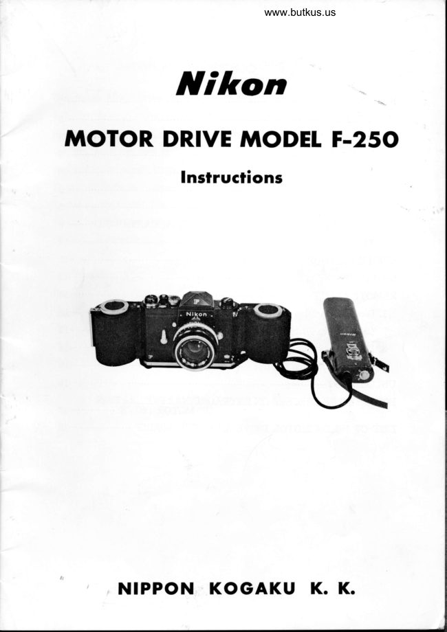
NikonPDF
Nikon Motor Drive Model F-250
User manual
22 pages · EnglishRead →
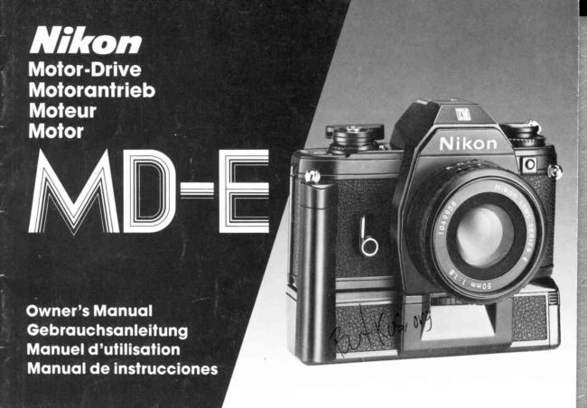
NikonPDF
Nikon MD-E
User manual
18 pages · German, SpanishRead →
NikonPDF
Nikon MD-2
User manual
32 pages · Not specifiedRead →
From the M. Butkus archive. Original publisher and archive notices are retained.
Check the model and edition against your equipment.
PDF verified 2026-10-10.