Flashes & lighting
Polaroid Acme-Lite Model 170s flash instructions User manual
User manual for Polaroid Acme-Lite Model 170s flash instructions. 15 pages in English. Read the original PDF, download or print a copy without registration.
15 pagesEnglish9.9 MB PDF
Loading your manual…Open PDF directly
Document details
- Brand
- Polaroid
- Model / document
- Polaroid Acme-Lite Model 170s flash instructions
- Document type
- User manual
- Language
- English
- Pages
- 15
- File size
- 9.9 MB
- Category
- Flashes & lighting
- Document date
- Not specified in catalog
Search available document text
Find a term, then jump to its page in the original PDF. Image-only pages may not be searchable; check the PDF for exact wording and diagrams.
Page 2 · Read text
ef af

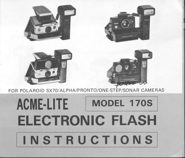
FOR POLAROID SX70/ALPHA/PRONTO/ONE-STEP/SONAR CAMERAS

ACME-LITE | MoveL 1705.
ELECTRONIC FLASH

INSTRUCTIONS
View original page 2
Page 3 · Read text
FOR PRONTO & ONE STEP


           FOR SXTO & ALPHA


          O MODEL 17OSwww.butkus.usELECTRONIC FLASH

lw*-
View original page 3Page 5 · Read text
WARRANTY
This electronic flash unit was quality inspected by our factory per-
sonnel before packing and found to be in good working order. To
ensure complete satisfaction, this unit is warranted to be free from any
defects in material or workmanship for a period of one year from
the date of purchase by the original owner. Registration card on back
of this instruction book must be completed and returned to the factory
within 10 days of purchase for this Warranty to become effective.
Should unit become defective within the period of this Warranty,
it should be returned to the factory for service, prepaid and insured.
Explain the nature of the problem and enclose $2.00 for handling
and return postage. Be sure unit is securely packed since the factory
assumes no liability for loss or damage in transit. Include any accessory
parts sold with the unit except batteries. This Warranty does not
cover damage to the unit because of abuse, misuse, dropping, or at-
tempted repair by anyone except factory personnel. Cost of repairs
after termination of this Warranty will be quoted on request. Warranty
does not cover batteries or  f ilm.

ACME-LITEwww.butkus.usMANUFAcTURING co..
340 1 MADISON  . SKOKIE, ILL 60076 . U.S.A.
View original page 5
Page 6 · Read text
MODEL 17OS
 Th is E lectronic F lash is un iversal for  all Polaroid cameras using
 SXTO  f ilm including models SX7A, Alpha, Pronto, One-Step, Pronto
 Sonar One Step, and SXTO Sonar One Step. Models having suffix
 -SE are included.
 fModel Cross Reference:
      O n e-Ste p          No. 1 OOO
       Pronto            No.2OOO,30OO
         Prontei Sonar       No. 5OOO

       SPECIFICATIONS

BCPS Rating                       1,300*
G u ide N umber (ASA2S feet)       42
Number of Flashes                         1 OO (Alkaline batteries)
R ecycle Time                   15 sec-18 sec
l\ngle of Flash                 V45o x HSOo
Flash Duration                   1/1OOO sec
Color Temperature              56000 Kelvin
Power Source                    Four AA Penlite Batteries
Maximum Distance              1O ft (glvl) all models except:
                               One Step        I  ft (2.5M)
                              SX70 Sonar   12tt (4M)
*Within 30 seconds after neon  lite goes oh, All ratings based on
 using Alkaline batteries.
View original page 6Page 7 · Read text
CAMERA ria                                   FRONT           BACK
SUPORT
BRACKET


Mr@M


        IDENTI FICATION OF PARTS
                    1.  F lash un it                           9a. Sonar Adapter w/cap
                  2. Connection Housing              9b.  Non-Sonar Adapter
                  3.  Locking Tongue                    10.  Bracket Hook
                  4.  Bracket Locking Screw            11. Side Bracket Clips
                  5. Synch Lead with Splice            12. Pronto Bracket Tongue
                connector                           13. Mounting Holes for Sonar
              6. Neon Lite & Test Buttonwww.butkus.us Cameras              7. On-off Switch                     14. Sonar Mounting Screw
              8. Battery Cover                      w/was her
View original page 7Page 8 · Read text
|-!


         BATTERY


     Slide back the battery cover (B) marked "Open" on the
    bottom of the handle. Insert four size AA Penlite batteries
     according to the polarity indicated inside the compart-
    ment. Push batteries down so that cover can be replaced.
    Note: Alkaline type batteries are recommended for maxi-
       mum power and optimum perforrnance.
    Turn the switch (7) to the "on" position and wait for the         TEST BUTTON
    Neon Lite (6) to gf ow. Depress Test Button (G) to verify        & NEON LITE
     batteries are operating. Repeat this 3-5 times to make
     su!'e condensor is working efficiently, Never leave bat-
     teries in storage compartment for long period of time be-
    cause of possible leakage. whenever using unit after long
    period of storage, repeat the test firing steps described
    above to reform condensor.
    Note: Camera shutter will not fire unless flash switch  is
           turned on and neon light is glowing. See page12"                                                                          H0lltt  l?,-:fi$
View original page 8Page 9 · Read text
CONNECTION

ATTACH FLASH TO BRACKET
Insert the tip of the Bracket Locking Screw (4) into the
threaded hole on the side of the bracket and tighten.
Notice the markings P and S on top of the Connection
Housing (21 as well as the index line at the top of the
bracket where  it fastens to the Housing.
Before tightening the locking screw, be sure that the pin
on the side of the camera bracket is properly aligned and
inserted into either the P or S alignment holes in the Con-
nection Housing (2).
Use P Alignment for Pronto, One-Step, and Pronto Sonar      I
camera models.
Use S Alignment for SX70, Alpha, and SX70 Sonar
camera models.
Once you have made the proper alignment, tighten the
Bracket Locking Screw @l securely. This alignment will
assure that the lens of the camera is parallel with the lens
of the flash to give even distribution of light from top to
bottom (see illustration at lef t).

   www.butkus.us
View original page 9
Page 10 · Read text
MOUNTING CAMERA
     Pronto ! One-Step, & Pronto Sonar
 fi,
                                                              the I     Starting with the back end of the camera, place
      camera onto the bracket spreading the Side Bracket Clips               w@i      (11) until the bottom of the camera rests flat on the      krnffi
      bracket. Then sfide the camera backwards making sure
       that the Pronto Bracket Tongue (12l' on the bracket slides
      into the grooved recess on the bottom of the camera.
       Slide the camera as far back as itwill go making sure it is
      securely held by the bracket. Use the Mounting Screw
     n4l (Remove washer under the screw head to make long-
I      er) to hold the Pronto Sonar model securely by inserting
         it into the bottom of the rear Mounting Hole (13) in the
       bracket and screwing it into the tripod hole on the bottom
       of the camera.


                                                                                                                PRONTO!
                                                                                                 & One Steo
View original page 10Page 11 · Read text
MOUNTING CAMFRA
           SX7O, Alpha, SXTO Sonar
                   Open the camera until it is locked. Place the camera onto
                   the bracket and push camera down into the bracket
                        spreading the Side Bracket Clips (1 1 ). When the bottom
                       of the camera rests flat on the bracket, the Clips will snap
                      over the edge of the camera. Slide the camera back until
                   the rear of the camera engages into the Bracket Hook
                           (10). check to make sure the camera is securely held. Use
                     the Mounting screw (14) to hold the SX70 Sonar model
                         securely by inserting  it into the bottom of the rear Mount-
                        ing Hole(13) in the bracket and screwing it into the tripod
                         hole on the bottom of the camera.
                    To prevent loss of screw insert screw into front hole, when
                     camera is not mounted on bracket.


sx 70
ALPHA

                     www.butkus.us
View original page 11Page 12 · Read text
ELECTRNCAT CONNECTION
 Included with your unit are two Power Adapters: one is
to be used with Sonar cameras; the other for non-Sonar
cameras. Be sure to use the proper Adapter to avoid
damage to  f lash and/or camera.
FOR SONAR MODELS: Be sure your camera is a Sonar
model marked on the front of the camera. Select Sonar
Adapter (9a). lnsert the Synch lead with splice connection
on the end of the wire (51 into the splice connection on
the end of the adaptor (9a). One side of the Adapter
has a single contact blade and is intended only for the SXTO
Sonar model; the opposite side of the Adapter has a double
blade and is intended only for the Pronto Sonar model.
Insert the correct contact blade into the model camera you
are using. Do not force the blades into the wnong camera.
After inserting the bfade(s) into the camera in the same
manne!" as inserting a flashbar, then use the cap to cover
the unused blade(s) on the reverse side.
FOR NON-SONAR SXTO/ALPHA/PRONTO/OIVE.STEP       :
Select the Non-Sonar Adapter (9b) which is marked Non-   ALIGNWITH HOLESPINS CAREFULLYAND ALIGNMENT NOTCH
Sonar. Insert the splice connection on the Synch Lead (S)                M ARKon the side of the flash into the splice on the end of the
adapter. Insert the contact blade into the camera in the
same way as inserting a flashbar after observing that one
side of the adapter is marked "Front".
When making the splice connection for either Adapter              NOTCH
take extrerne caution to properly align the prongs and  PUSH ALL THE
                                                                                                      INinsert slowly so as not to cause darnage to the delicate  WAY                                                     BUT DOpins. Use Alignment notch and marks in the splice con-        NOT FORCE
nector and in the adaptors to insure proper connection.
                                                                                                    r0
View original page 12Page 13 · Read text
PICTURES

Take your pictures in the normal way you would with a
Flashbar. Load the film, compose the picture, focus the
lens, and press the shutter. The flash will fire automatical-
ly when the shutter is tripped.
Make sure the Neon Lite (6) is always on before taking
the picture, preferably waiting about 30 seconds after the
neon glows for maximum power. When the flash fires, the
neon lite will go out and then come back again indicating
the flash can be fired again. This recycling will take pro-
gressively longer as the batteries become weaker. When it
takes more than 75 seconds for the neon light to come
back on, a fresh set of batteries should be inserted. When
taking pictures, try to place subjects in front of light
colored background to take advantage of reflection. Much
valuable illumination can be wasted without a background
that reflects light back onto the subject,

   www.butkus.us
View original page 13
Page 14 · Read text
IMPORTANT

Certain important safeguards to insure optimum results and satisfac-
tion with your camera and flash and to guard against spoiled pictures
and wasted film have been built into the camera and flash unit which
the user should be aware:
1. Neither flash nor camera will operate unless the camera is loaded
   with a filmpack which contains the camera's batteries.
2. The camera and flash will not operate if the flash switch is turned
  OFF. lf the camera does not work, check the flash switch which
   you may have forgotten to turn back on.
3. The camera and flash will not operate if the neon light is not on.
   This is to make sure that there is adequate power in the flash to as-
    sure good exposure.
4. The neon light will not go on until a minimum of 85 % of the flash
   power has been attained to make sure of sufficient illumination.
   This might make the neon light seem slow to recycle but this is
    better then a premature neon without sufficient power.
5. When the electronic flash is not needed for taking picturers, be sure
   to disconnect the flash from the camera so that the electronic con-
    trols stated above are made inoperative.
This Electronic Flash has been designed so that it's electronic circuit is
integrated into the electronic circuit of the Polaroid camera thus en-
abling the combination of the two to provide maximum satisfaction.
View original page 14Page 15 · Read text
7

         INSTRUCTIONS FOR ONE STEP CAMERAS
               These instructions refer only to the Non-Sonar One Step (Model 1000)
               cameras and not the Sonar One Step models. Because of the special
                 optical system used in the One Step camera, extra precautions should
                be taken when using electronic flash with this camera:
               1. TIME DELAY SYNCHRON IZAT ION: The electronic shutter used
                      in the One Step is timed to synch with flashbars and not electronic
                       flash. However, this flash unit includes a special Tir-ne Delay circuit
                 which adjusts the synchronization to permit its use with the One-
                      Step.
              2. LENS SPEED: The extremely slow lens used in the One Step
                       limits the use of both flashbar and electronic flash to no less than
                 5 feet n.75 M) and no more than B feet (2.5 M).
             3. F IXED APERTUR E: Unlike other Polaroid SX70 cameras, the One
                Step does not have a diaphragm in its optical system and uses a
                 fixed rather than variable aperture. This admits a constant amount
                  of light onto the film which tends to over- or under-expose. To
                     adjust for this condition, follow these rules:
                a. Attempt to take pictures 6 feet Q$ M) from subject at which
                      point the light is properly balanced for the fixed aperture.
                b. To make your picture darker and overcome overexposure  less
                     than 6 ft. take picture immediately when neon light goes on.
                 c. To make your picture liEhter and overcome under exposure over
                  6 ft. take picture about 30 seconds after neon light goes on.
              Under all circumstances uses a reflecting background to pose subjects.
                                www.butkus.us
     r3
View original page 15Related documents and language editions
PolaroidPDF
POLAROID 220
User manual
37 pages · EnglishRead →
PolaroidPDF
POLAROID 350
User manual
53 pages · EnglishRead →

PolaroidPDF
Polaroid 108 film information
User manual
5 pages · EnglishRead →
PolaroidPDF
Polaroid 110A
User manual
30 pages · EnglishRead →

PolaroidPDF
Polaroid 125
User manual
23 pages · EnglishRead →

PolaroidPDF
Polaroid 135
User manual
25 pages · EnglishRead →

PolaroidPDF
Polaroid 210
User manual
27 pages · EnglishRead →

PolaroidPDF
Polaroid 215
User manual
25 pages · EnglishRead →

PolaroidPDF
Polaroid 225
User manual
29 pages · EnglishRead →

PolaroidPDF
Polaroid 230
User manual
28 pages · EnglishRead →

PolaroidPDF
Polaroid 240
User manual
27 pages · EnglishRead →
PolaroidPDF
Polaroid 3000 Wink Flash
User manual
13 pages · EnglishRead →
From the M. Butkus archive. Original publisher and archive notices are retained.
Check the model and edition against your equipment.
PDF verified 2026-10-10.