Film cameras
ZEISS IKON IKOFLEX I User manual
User manual for ZEISS IKON IKOFLEX I. 17 pages in English. Read the original PDF, download or print a copy without registration.
17 pagesEnglish1.9 MB PDF

Loading your manual…Open PDF directly
Document details
- Brand
- Zeiss Ikon
- Model / document
- ZEISS IKON IKOFLEX I
- Document type
- User manual
- Language
- English
- Pages
- 17
- File size
- 1.9 MB
- Category
- Film cameras
- Document date
- Not specified in catalog
Search available document text
Find a term, then jump to its page in the original PDF. Image-only pages may not be searchable; check the PDF for exact wording and diagrams.
Page 5 · Read text
24
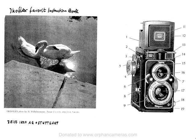
               23  :  Knob  of spool-holder   in  lower  spool  dramber
                  24:   Pin  for  holding  spool  in  feed  chamber
               25  :  Pin  for  holding  spool  in  take  up chamber
                           (wooden   or  metal-spool)

Importantt  Before loading  the camera with  film  it  is necessary to practice the few
operations  in order  to avoid any  trouble  due to unfamiliarity   with  the  controls

4

                 www.orphancameras.com
View original page 5Page 6 · Read text
l. The film spool
The Ikoflex  I takes pictures 2rlt" squ,are (6X6 cm), and is loaded with the normal
120 size rollfilm.  In the lkoflex,  this film gives 12 exposures in  t}l.e 2r/r" square
format.
The spools of  film are  light-tight when  the end  of  the backing paper  is stud<
down, but  it  is always advisable to Ioad and unload the camera in diffused day-
light  or  else in the shade, Direct sunlight should not be allowed  to strike  the
spools. Always wind the film and codr the shutter first before pressing the release
button.

ll. loqding rhe comercl
1. The knob  (18) is moved  in the  direction
    of the arrow  and the camera back simul-
   taneously  pulled  open.
2. The knob  attached to the pin holding  the
   spool  in  the lower  or  feed chamber  (23)
    is now  pulled  out and turned  slightly  to
   lock   it  in  the  outer  position.  The   full
View original page 6Page 7 · Read text
spool  of  film  is placed on the right-hand
                      (fixed) pin in the lower  or receiving  spool
                 chamber: the pointed  end  of the backing
                 paper must point towards  the other spool
                 chamber, and the black  side  of the paper
                 must  face  inwards.   The  knob   (23)  is
                  then  turned  back, and  the peg  allowed
                     to  enter  the  circular  hole  bored  in  the
                  core  of the  full  spool.  The  spool  is now
                  held  firmly   in  place.

                 3. The paper  strip holding  down  the point-
                ed end  of the backing paper  is now  bro-
                  ken, and the backing paper  itself  pulled
                   out  over  the  open  back  of  the  camera
                      until    its  pointed  end  can  be  pushed
                 through the larger  slot of the empty  spool
                       in  the upper  chamber.

                  4. By  turning   the  film  winding   knob   (5)
                 round  once  or  twice,  the paper  is  tight-
                ened and a  little  of   it wound  on  to  the


www.orphancameras.com
View original page 7Page 8 · Read text
spool.  The  paper  must  run  evenly  bet-
   ween  the flanges  of the  spool: should   it
   chafe or rub  the flanges,  it must be loos-
   ened  and  made   to  run   flat  between
   them.

5. The camera  is then  closed  by  pressinq
   the hinged  back  firmly  against  the main
   body.  The  lock must  snap  audibly   into
   place.

6. The  cover  over  the  red window   (22) in
    the back of the camera  is now  slid away,
   and the film winding  knob  (5) turned  for-
   ward  continuously  until  a hand appears
    in  the  red window   (22).  This  is a war-
   ning  sign, and just  after  it the number'I'
    will  appear. As soon as the number   'l'
   appears   in  the  red  window   the   first
   section  of  film has been wound  into  the
   focal plane  of the camera and  is readv
    for exposure.
View original page 8Page 9 · Read text
The  red  window    is now  covered  once
               more  with  the  slide,  in  order  to  avoid
                any  risk  of fogging  a panchromatic   film.

                lll. Unlooding rhe ccrmercr
                 1.  After  the  last  (i. e. twelfth)  exposure  has
               been made, the  film winding  knob  (5) is
                 turned   continuously      f orward   until   the
               end of the backing paper has moved  past
                  the  red window   (22).
                2. The camera back  is then opened as des-
                  cribed  on  page  6, and  the  end  of  the
                backing paper on the exposed  film spool
                 sealed  down   firmly   with   the  gumstrip
                 provided.  The knob  (19)  is now  pulled
                 outwards, locked  in the outer  position  by
                  turning   it  slightly, and the exposed spool
                      lifted    f rom  its holder.
                3. The knob (23) in  the  lower spool chamber
                       is then  pulled  out and held  in  the outer


www.orphancameras.com
View original page 9Page 10 · Read text
position by turning   it  slightly. The empty
    spool  from  which  the  exposed  film  has
   been unwound,  is then removed and pla-
    ced  in  the  upper  spool  chamber.  One
   end  of the spool has a circular  hole and
    the  other  a  circular  hole  with  a cross-
     slot:  the  slot  must  be  placed  on  the
   same side as the  film winding  knob  and
    engagecl  with   the  metal  dogs  on  the
    winding  knob  peg  (25) so that -the spool
     is  carried  round  with   the  knob.  The
   knob    ( 19)  is  then  turned   slightly  back,
   and   will  spring  inwards  and  hold  the
   empty   spool   firmly    in   position.   The
   camera  can then be loaded  with  a new
    spool  of  film.

lV. Tcrking the picture

The  picture   to  be  taken   is  focussed  and
composed on the ground-glass  screen inside
View original page 10Page 11 · Read text
the  finder  hood.  That  part  of  the  subject
                                      which   is  in  sharp  focus   is  shown  by  the
                                      depth  of focus  scale  (20) placed  next  to the
                                        focusing  control  knob.  As may  be seen  in
                                          the  illustration,   at   f ltt  ob j ects  at  all  dist-
                                    ances between  about  6 and  15 feet  will  be
                                      sharp when  the  focusing  distance  is   I  feet.


                                  1 . Move  the  lodcing  button  (17) to the  left,
                                         as  shown,  and   the   finder  hood    will
                                            spring automatically  into position  for use.
                                              )   In  use,  the  camera   is  slung  round  the
                                        ned<, and adjusted  to a convenient height
                                         by  altering  the length  of the  strap used.

                                 On  glancing  down  into  the  finder  hood,
                                       an  upright  picture   of  the  scene  before
                                             the camera  will  appear.  This  picture   is
                                          reversed  left  to  right,  as is the case with
                                                             all  reflex  cameras.

1 0
                 www.orphancameras.com
View original page 11Page 12 · Read text
In  order to obtain  critical  focus, particularly
when  using large lens apertures,  it  is praeti-
cal  to use the focusing  magnifier  (14).


3.  After  pushing  down  the  right-hancl  side
   panel  (1) of the  finder hood, the  built-in
   magnifier  is raised with  the  forefinger  of
   the  right  hand  by means  of  the  lug  on
    its side.


  When  focusing,  the eye must be directly
   over  the  centre  of  the  magnifier.

                                                                 1 1
View original page 12Page 14 · Read text
.,                                                                                               .                                                                           ':
Prevention  of double exposures
 It.is idpossible  to expose one section of the film twice, since the shutter will  not
 operate until the winding knob (5) has been turned forward, and a new,section of
 film wound  into the focal plane of the camera.
 winding  on is indicated in the window  (2) by the appearance of a red disc. when
the disc can be seen, the film has been'wound  on,'jnd'.eteurirrq   th"  shutter will
expose a fresh section. Always  wind  the film and coct-ttr"   sit'"tiei  first belorepressing the release button,
Two-point focus settings
                             t_l                         is_impossible_to                                         focus                                                     rapidly                                                enough                                                                 ground                                                        on the                                                                                      glass. ll_"T.":-p!:i:i_:":_"ir'or this purpose the                        lkoflex                                       is fitted with                                            the                                              Zeiss lkon                                                         iystem                                                                            of                                                                    iwo_point                                                                                                              fixfocus setting
 ft:           ape-rt-ure                      adjusted  in advance to the red dot on the scale between  f/B        l,"r                          -is
an(r t/rr, and the focusing distance also adjusted to the red dot between 20 and
30 feet on the scale. with  these-two  settings, everythiirg-b"iw"""'rs     feet and
i$nity    qifl  be-in.sharp focus, and  if the shuiter time is               of a second,
it  will  seldom be necessary to make any adjustments whatever"itio,v*,iiio  thi  cam"r.   in
normal snapshot woik,  where ladc of time sornetim"r;;kJ;        ii;"ioiil"       questionto focus critically.
The. exposu-re given  at                                settings is enough to give .well exposed negatives                        .theseeven in dull winter  weather.

                                                                         $
View original page 14Page 15 · Read text
/
The lens operture
The lens aperture  is adjusted by moving the Iever  (9) to one side or the other.
The apertuie numbers are indicated on the scale seen through the window  (11).
The larger the aperture number, the smaller the size of the aperture of the lens'
and the gireater the depth of focus-but also, the larger the aperture number, the
longer must be the exposure under the same light  condition.

                            Seffing the shutters
l l                                  The  Compur-shutter   gives  snapshot  exposu-
t 2                                         res  of  1 second  to  l/sooth second, and  long
                                              or  brief  time  exposures.


                                 S n a p s h o t     e x p o s u r e s :

                                   The  ring   (7)  is  turned   until   the  required
                                            shutter  speed has appeared  in  the  window
                                                                   ( 10). The  numbers  seen mean  fractions   of
                                        a second.  The  shutter   is then wound  up by
t4
                  www.orphancameras.com
View original page 15Page 16 · Read text
moving lever (8) along in its srot and released by pressing the button (3). A flexible
        cable release may alternatively be used; and  it  is screwld  into the nipple of the        button  (3).
        Important: when  the shutter has been set, do not be ctrange from a srow shutter
       speed to its highest speed, since this would put too much of a strain on the inter_        nal mechanism.
                           Turn ring (7) until the letter ,,B,,appears in the window         Il,*"."*.p?:.rtgt:
          (ru, ano wrno the shutter. A pressure on the release (3) will then open the shutter,
       and the latter  will remain open until the pressure on the release is relaxed.

                                                                                                                                                                 l l
                                                                 8
                                                               r0


       The Pronto-shutter  gives  snapshot exposures
t         of   I second to  l/z;oth second. The instruction
           is  the  same  as  above.    In  addition   the
        Pronto-shutter  has  a  release  for  delayed
tI       action  (lever  Nr. 26).
View original page 16Related documents and language editions

Zeiss IkonPDF
Zeiss Ikon IKOFLEX Guide
Reference guide
35 pages · EnglishRead →

Zeiss IkonPDF
Zeiss Ikon Ikoflex
User manual
17 pages · EnglishRead →

Zeiss IkonPDF
Zeiss Ikon Ikoflex IIA
User manual
32 pages · EnglishRead →

Zeiss IkonPDF
Zeiss Ikon Ikoflex III 23 - 24 pgs. missing
User manual
26 pages · EnglishRead →

Zeiss IkonPDF
Zeiss Ikon Ikoflex Ia
User manual
29 pages · EnglishRead →

Zeiss IkonPDF
Zeiss Ikon Ikoflex Ib
User manual
31 pages · EnglishRead →

Zeiss IkonPDF
Zeiss Ikon Ikoflex Ic
User manual
32 pages · EnglishRead →

Zeiss IkonPDF
Zeiss Ikon IKOFLEX 1A
User manual
18 pages · FrenchRead →

Zeiss IkonPDF
Zeiss Ikon Ikoflex 1A numérisation d'une seule page
User manual
26 pages · FrenchRead →

Zeiss IkonPDF
Zeiss Ikon Ikoflex IIa Gebrauchsanleitung
User manual
32 pages · GermanRead →
Zeiss IkonPDF
ZEISS IKON IKOFLEX
User manual
16 pages · Not specifiedRead →

Zeiss IkonPDF
Zeiss Ikon a guide to the IKOFLEX I-a
Reference guide
12 pages · Not specifiedRead →
From the M. Butkus archive. Original publisher and archive notices are retained.
Check the model and edition against your equipment.
PDF verified 2026-10-10.