Film cameras
Zeiss Ikon Ikoflex III 23 - 24 pgs. missing User manual
User manual for Zeiss Ikon Ikoflex III 23 - 24 pgs. missing. 26 pages in English. Read the original PDF, download or print a copy without registration.
26 pagesEnglish5.1 MB PDF

Loading your manual…Open PDF directly
Document details
- Brand
- Zeiss Ikon
- Model / document
- Zeiss Ikon Ikoflex III 23 - 24 pgs. missing
- Document type
- User manual
- Language
- English
- Pages
- 26
- File size
- 5.1 MB
- Category
- Film cameras
- Document date
- Not specified in catalog
Search available document text
Find a term, then jump to its page in the original PDF. Image-only pages may not be searchable; check the PDF for exact wording and diagrams.
Page 4 · Read text
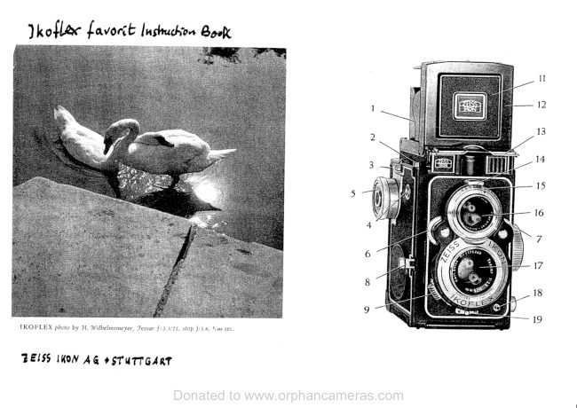
6 :  Handle with hinged end which winds on the film and sets the
                 shutter.
            '7_t-   Lever for setting the delayed-action shutter mechanism.
       B; Indicator showing whether film is in the camera or not.                                            .                                                                                                   \       9- Lever for adjusting the shutter speed.
      IO: Nipple taking flexiirle shutter release.
        1l:  Camera taking lens.
        t2:  Coloured indicator: shows red when shutter is set, black lthcn
             not set, and white when delayed-action mechanism has been set.
        t3:  Lever for setting lens apertures.
      L4: Finder lens.
        t5: Vindow for reading off lens apertures
      L6: Vindow for reading off shutter speeds.
             I.7 :  Front panel of view fjnder hood, contairring'van Albarla type finder
             with parallax compensation.
         lB .- Sullplementary focussing magnifier.


L
View original page 4Page 5 · Read text
butkus.us


         4   Eyelet for swivel of carrYing            -  strap.I 19   Black sight of view finder in            -               hood.
       20: Left side panel of finder hood.
         2l   Button which openE the finder            -               hood.
       22: Lod<ing button of camera badc.
        23  Knob for holding sPool in            -            take-up dramber.
        24   Depth of focus scale.            -
        25 -  Focussing control knob.        26  Knob for holding spool in feed            -              dramber.

        4
\
View original page 5Page 6 · Read text
27                29

23   Knob for holding spool in take-up dramber.   -26  Knob for holding spool in feed dramber.   -27   B"g for holding spool in feed chamber.   -28          key in take-up dramber.  -'Winding29    fnclicating clots for loarling film.   -
View original page 6
Page 7 · Read text
butkus.us
General notes

                                                                                                                                                                                                          .lThe novel design of the Ikoflex III makes it necessary for the user to read
the following instructions carefully.  It is only when the various move-
ments have been thoroughly understood that  successf ul  results in
practice can be expected.
                                                                                'itThe Ikoflex III  is designed in such a way that    is imlrossible to forget
any particular operation between exposures: the crank handle winding
on the film turns through 180o, and if  not turned through its  full
distance will not return to its original position.
This crank sets the shutter as it moves on the film to the next picture:
by this means double exposures as well as blank unexposed sections of
film are completely prevented
A picture counter indicates the number of exposures which have been
made, and after the l2th exposure the counter springs back to zero as
soon as the crank handle is wound, remaining there until a new film has
been loacled. As soon as the first section of film has heen wotrncl into
llosition the handle is Llt'hed anrl r:itttnol lrrr rnoverl:tg:tilt rrrrtil irn ex'
posure has been made.                                                                                                                                                                                ':-l

6
View original page 7Page 8 · Read text
t'\

f. Suitable films to use.
The 'Ikoflex takes pictures 2rltx.2|la inches (6x.6 em) in size, and is used
with a standard B 2 wide tliameter spool, on which it gives 12 pictures.
The fast Zeiss Ikon Pant'hrom film is specially r""o-L"nded, since it
is always' reliable and gives excellent results even in had lighting contlitions.
The colour sensitivity of this film inclurles orange u"I      u, well as
the other colours, and all colours of the rainbow ur" ,"1r*oducecl"ud,-   in theircorrect relative brightnesses.
Spools of film rnust be kept in their original light-tight cartons ald
wrappings, and although the backing paper is impervious to light it  is
desirable to load and unload the camera in diffused weak liglt  or in
the shade" This will avoid any risk of fogging.


                   Zeiss lkon catneras                                            -  Zeiss lenses -  Zeiss lkon film
              These three rrlean trouble  - free photo graphy                                     -l

                                                                                                                                                                                                                                                   f'{i
View original page 8Page 9 · Read text
butkus.us
II. Loading the camera
Under the crank handle (6) will be
seen a small indicator (8). When
no film  is in the camera, a dark
area is seen through the circular
windowo but when a film has beerr
loaded into  the camera and  its
paper backing strip attached to the                             ooF"take-up spool, a large white      on
a red ground appears in the window
(8). It  is thus possible to ascertain
in a moment whether film is in the
camera or not.
The following operations are  re-
quired for,. loading, and must he
carried out in the orcler given below:
I. By moving the button (22) in
   the direction of the arro\tr' and
    simultaneously lifting the back of
   the camera, the latter swings gpen
   on its 'hinge.

B
View original page 9Page 10 · Read text
2.  After  pulling outwards slightly
   the knob (26) and turning it  a
     little to the side to lock it in the
   outer position, a  full spool of
    film is placed orr the inside pin
   (27). The pointed end of  the
   bad<ing paper must point in the
    clirection of  the open camera
   back and the take-up chamber,
   the black surface being next to
   the camera body and not facing
   upwards. By turning the pin (26)
   bad< to  its original position, it
    will spring inwards once nlore
   and hold the epool of film in placr:.
.3. The gumstrip holding down the
   baeking paper of the film is now
   broken, and the paper clrawn
   over the open camera llack and
   threaded through the longer slot
   in the empty spool core placed
   in the take-up dramber.
View original page 10Page 11 · Read text
butkus.us

                                                                                     ir{. Move the crank handle (6)
    little,  until the two  triangular
   bla& marks on the bad<ing PaPer
   are opposite the two white intli-
   cating dots (29) on ihe guides
   beside the    f ilm  in  the  oPen
   camera badc.
J.  The camera bad< is now closed,
   rnaking certain' that the locking
   button snaps audibly into Place.
6. The crank handle (6) is turned
    until the first section of film  is
   ready for  exposure inside the
   camera.'aThis is the case when
   the handle (6) locks, and will not
   turn further. SimultaneouslY the
                                                                     'L1.1)    picture counter (3) indicates
   on its dialt and the shutter is set
   so that an exposure may  lte
  made iromediately.
l0
View original page 11Page 12 · Read text
III. Taking the pieture
Focussing and coruposing the picture
are clone on the ground-glass screen
of the view-finder. The depth of
focus is indicated lry the  specill
scale (21) placed beside the focuss-
ittg control knob, and showing the
limits of sharp  f ocus for any lens
aperture which may be in use. In
the illustration opposite, the subject
focussed ie at 6 feet, and if may
lre seeen that at f ln  the limits of
focus are 5 and B feet.

1. Pressure on  the  button  (21)
   causes the hood of the finder to
   spring automatically into        . its
   working position.


ll

                                                                                                                                                                                       /
View original page 12Page 13 · Read text
butkus.us
,  For use, the Ikoflex is hung
   round the neck on a strap, anrl
    its height belo*' the eyes may
   be adjusted by moving the buekle
   of the strap itself.
   The image seen inside the finder
  hood is brilliant and erect, but
      as in all reflex cameras       it    -                  left to  right.    -
     :t ."""":r"O

:1.  For the very sharpest focus, par-
    ticularly at large aperture values,
     it  is useful to use the supple-
   mentary focussing magnifier (18).
   This springs upwards into  posi-
   tion when the small millecl lever
   (2) is pressed downrvards.


L2
View original page 13Page 14 · Read text
-1. During use, the eye should be
    placed close to the magnifier ancl
    just over its central point.


   After focussing, the magnifier in
    its mount is plushed clownwards
   once rnore, and it will rernain in
   that grosition.


l3
View original page 14Page 15 · Read text
butkus.us


.).  V-hen retluiretl, tht: caltlera lna)
   also lle trsed at eye level, for a
   van Alltada type finder is  btrilt
   into the finder hood for  this                                                                                                                                                                    f intlcr hooti is   l)urpose. The aperture (I9) in the batk lranel of the    i,r"d fo" an eyepiece, but before using it' the rnagnifier (18) must be
   raised so that vision is not obstructed.
   The van Alllatla tylle finder is an irnmense imllrovernent over all other
    direct-vision finders  for the photography of rnoving objects, for it
   shows a considerably greater portioi oi  itt" subject than is actually                               'All                                    olljects are seen in their natural size, and   taken by the                   "u-".".                                                                                                                                                         f inder is that the   the atlvantage                over the ordinary   f rame !yp" of    limits of th; camera field are ,""n as white lines projected at the
   subject distance.
l4
View original page 15Page 16 · Read text
This is arranged by the unusual design of the finder itself: the white
   rectangle is       on the back wall of the finder surrounding th9                ""tnully              by the eye as a sight. The glass of the front portion of   aperture used
  the finder consists of two cemented lenses, the surface between the
  two |eing semi-silveredo and as a result this semi'reflecting surface
   lrrorluces an image of the white rectangle at the subject distance.  The finder rnust be held close to the ele,, so that the area surr-
  ounding the white rectangle can be clearly seen' though the area
                                                                          be   en"losfi |y the white lirres themselves is that which will actually
   inclutled in the picture taken by the camera lens. The front wall of
   the finder hood (I7) moves as the focussing control knob is turned,
  and thus compensates for variation in parallax at differerrt focussing
   distances. By this means it  is ensured that what appears within the
                                                                        nega-   white lines seen through the finder will actually appear in the
   tive later oIr.


                   Zeiss lkon cameras  Zeiss lenses -  Zeiss lk'on film
             These three  n't'earu troubl"'lree   photography

I5
View original page 16Page 17 · Read text
butkus.us
6. Focussing is  watched on  the
   ground-glass screen while  the
   control knob (25) is turned, and
   the shutter release (5) is  best
   pressed to make the exposure by
   the right thumb.


1a. When using the  longer oosnal)
   shot'o exposure   times   it     is
   strongly decirable  that after the
   focuesing has been adjusted, the
    left hand steadies the camera as
   shown opposite.


l6
View original page 17Page 18 · Read text
I(
              8. When it  is required to  work
            with the delayed-action shutter
             release, the mechanism controll-
             ing this action, must first be set.
           This is done by pressing the
             frutton (7) on the camera front
           upwards in its slot until  it  will
           go no farther. The indicator (12)
            of the shutter will then show the
            white disc.
         The  delayed-action mechanisnr
            cannot be used for rfaooth second
          and 668" settings.

              9.  Af ter each exposure, the crank
                (01 is turned throush             bllit"           1800, whir*r will move on  tf,e
              film, wind the shutter againo anrl
           move the picture counter forward
            to the next number.

          l7
View original page 18Page 19 · Read text
butkus.us
Closing the finder hood
To close the finder hootl, the two side panels (l) and (2) are first folded
tlown, then the front panel (l?), and finally the bad< panel (19).
Safety devices
f)ouble-exposures on a single section of film are out of the question,
for the shutter can only be released when the film has been wound on
to the next picture. In the same walr the film eitnnot be wound on
rrrrtil the shutter has been released.
Apart from this mechanism, a  retl
disc shows in the window (I2) when
the shutter has heen set which also
means that the film has been wound
on. A blad< disc in the same window
indicates that the film needs wind-
ing on if another exposure is to be
made, and that the crank handle (6)
must be rotated.


I8
View original page 19
Page 20 · Read text
I

If the crank handle (6) and the shutter release (5) are locked, force must
never be used to try to make them work. Locking of one or the other
merely implies that some operation has been forgotten.

Two-point foeus settings
In order to give the very greatest readiness for use at short irotice, the
Ikoflex III   it  fitted with the well-known Zeiss Ikon system for two'
point focus settings. If  the lens aperture is set to the red dot between f  ll'L
ind f 116, and the focussing control knoti to the similar red dot betweenZO and 30 feet, the depth oJ fo"or stretches between 13 feet and infinity.
                                                                                                        la,:kThis setting can be used for practically every exp_osure in which
of time foibids accurate focussing on the ground glass.


 19
View original page 20Page 21 · Read text
butkus.us
The lens aperture
The larger the nunrerical value ,rf
the lens aperture, the smaller the
actual aperture through which light
passes, and the greater is the depth
of focus. At the same timeo a srnall
aperture (i. e. large aperture num-
ber) implies a long exposure. The
aperture is adjusted by rneans of
the lever (13).

The lens aperture that has been set
appears in the small rvindow (15).


  For the linest results ol all
 Zeiss  Ikon    lilm

20
View original page 21
Page 23 · Read text
butkus.us
       Short tl:.'e exposures
      More th" lever (9) until the lett,:i "B" appears in the window (16).
       For
       long time eposures.
       the s1ie,;ial flexihle release illustr'  -l  shoultl be usetl, and this is st.rervt'rl
       for rt*e in the nipple (10) on tL    .;, rttter casing. It differs frorn norrnal
         flexiblr' :eleases in having :r moi','able plate (R) between the plunger 1A)                                                     uB"      and the       (C).. Vhen the sirtr,icr ltas been set to     as alrove" the
       iiaves r ill"odyol)en when the pluuger (A) is pri'ssed, and rvill rernain ol)en
       ur rii  tLi , plate (B) is pressetl down
       against tl e body (C) of the release.
      This special release can lte used :rs
     a nornlal one   f or short time ex-
       [)osures lry pressing the lllate  (l])
         agairrst the body (C) and tttrtring  it
        slightly to the rigtrt to lock it  dorn'rr.
       Wherr this has lleen tlone, the plunger
       (A) is not lotked when pressetl down,
      and the release may be rtsetl in the
      normal manner.

        22

\/
View original page 23Page 24 · Read text
1
   vided, and the film repr&.ed;I in  ite original wrapping. To remove
   the full spool, the peg (23) lmust be pulled outwards, and turned
    slightly to lodr it in the outerl poeition.
  Py pollirrg out the peg (26) ini the .eme way as when loading a film,   the empty spool core mry be, removed from the feed dramber rnd
    transferred to the take-up &{mbcr.

  Vhen placing the spool in  'the
   take-up chamber, care mutt be
   taken that the slotted end of ':he
   core engages in the k"y  (28).
   The peg (23) will spring bed< and
   engage in the round hole at rhe
   other end of the core when it  ie
   turned badc to  its origlnel po-
    sition.

                  Zeiss IEon comerat -  Zeiss lenses -  Zeiss Ikon film
              These three tnean troubl"- lree photogrophy

25
View original page 24Related documents and language editions

Zeiss IkonPDF
ZEISS IKON IKOFLEX I
User manual
17 pages · EnglishRead →

Zeiss IkonPDF
Zeiss Ikon IKOFLEX Guide
Reference guide
35 pages · EnglishRead →

Zeiss IkonPDF
Zeiss Ikon Ikoflex
User manual
17 pages · EnglishRead →

Zeiss IkonPDF
Zeiss Ikon Ikoflex IIA
User manual
32 pages · EnglishRead →

Zeiss IkonPDF
Zeiss Ikon Ikoflex Ia
User manual
29 pages · EnglishRead →

Zeiss IkonPDF
Zeiss Ikon Ikoflex Ib
User manual
31 pages · EnglishRead →

Zeiss IkonPDF
Zeiss Ikon Ikoflex Ic
User manual
32 pages · EnglishRead →

Zeiss IkonPDF
Zeiss Ikon IKOFLEX 1A
User manual
18 pages · FrenchRead →

Zeiss IkonPDF
Zeiss Ikon Ikoflex 1A numérisation d'une seule page
User manual
26 pages · FrenchRead →

Zeiss IkonPDF
Zeiss Ikon Ikoflex IIa Gebrauchsanleitung
User manual
32 pages · GermanRead →
Zeiss IkonPDF
ZEISS IKON IKOFLEX
User manual
16 pages · Not specifiedRead →
Zeiss IkonPDF
Zeiss Ikon a guide to the IKOFLEX I-a
Reference guide
12 pages · Not specifiedRead →
From the M. Butkus archive. Original publisher and archive notices are retained.
Check the model and edition against your equipment.
PDF verified 2026-10-10.